
APLICACIONES AUTOMOTRICES
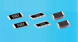
Resistor de precisión de película delgada 0.01%, TC2ppm, con cable de unión, anticorrosivo, MELF. Detección...
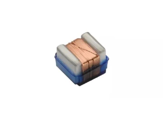
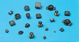
Lee masCon sede en Taiwán, Viking Tech Corporation es uno de los principales fabricantes de Inductor de chip de alambre enrollado SMD (Serie WL WL02JT16N) desde 1997.Cumple con las normas TS16949/ ISO9001/ ISO1400, cumple con los estándares AEC-Q200 y los productos se utilizan en aplicaciones automotrices y de dispositivos electrónicos.Viking ofrece resistencias de precisión anti-sulfuro, anti-sobretensión, de pulso, de alto voltaje y alta potencia, incluyendo resistencias de película delgada/ gruesa, resistencias automotrices, resistencias MELF y resistencias de detección de corriente.Inductores de bajo ruido, bajo coeficiente de temperatura (TC), alta potencia, como inductores de RF, inductores de chip, inductores de potencia, inductores variables, inductores de chip de ferrita, inductores blindados, inductores de hilo enrollado e inductores de inmersión.Viking ha estado ofreciendo a los clientes resistencias de potencia, inductores de potencia y condensadores electrolíticos de aluminio de alta calidad con una sólida reputación.Con más de 20 años de experiencia, Viking se especializa en la fabricación de Resistores de Película Delgada, Resistores de Chip, Inductores de Potencia, Resistores de Sensado de Corriente, Resistores de Película Gruesa, Capacitores de Chip y Substratos Cerámicos.
Inductor de chip cerámico enrollado en alambre, alta frecuencia, inductor RF para alta SRF, excelente Q, estabilidad térmica superior. Inductancia estable en circuitos de alta frecuencia. Diseño altamente estable para necesidades críticas.
WL Series0402 ±5% 16nHμH 0.22 Ω 560mA 24 3.1GHz
| Tamaño | Tolerancia | Inductancia | Condición de prueba | DCR (Ω) máximo. | IDC (mA) | Q | SRF |
|---|---|---|---|---|---|---|---|
| 0402 | ±5% | 16nH | 250MHz | 0.22 | 560 | 24 | 3.1GHz |
WL03(H) Wire Wound Chip Inductors / High Current Type
| Inductance (nH) | Tolerance | L Freq. (MHz) | Quality Factor min. | SRF (GHz) min. | DCR (Ω) max. | IDC (mA) max. |
|---|---|---|---|---|---|---|
| 1.6 | ± 5, ± 10% | 250 | 24 | 12.50 | 0.030 | 2400 |
| 3.6 | ± 5, ± 10% | 250 | 24 | 5.90 | 0.048 | 2300 |
| 3.9 | ± 5, ± 10% | 250 | 25 | 5.90 | 0.054 | 2200 |
| 6.8 | ± 5, ± 10% | 250 | 35 | 5.80 | 0.054 | 2100 |
| 7.5 | ± 5, ± 10% | 250 | 38 | 3.70 | 0.059 | 2100 |
| 8.2 | ± 5, ± 10% | 250 | 38 | 3.70 | 0.060 | 2000 |
| 10 | ± 2, ± 5, ± 10% | 250 | 38 | 3.70 | 0.071 | 2000 |
| 12 | ± 2, ± 5, ± 10% | 250 | 38 | 3.00 | 0.075 | 2000 |
| 15 | ± 2, ± 5, ± 10% | 250 | 38 | 2.80 | 0.080 | 1900 |
| 18 | ± 2, ± 5, ± 10% | 250 | 40 | 2.80 | 0.099 | 1900 |
| 22 | ± 2, ± 5, ± 10% | 250 | 42 | 2.40 | 0.099 | 1800 |
| 24 | ± 2, ± 5, ± 10% | 250 | 42 | 2.40 | 0.105 | 1800 |
WL02(H) Wire Wound Chip Inductors / High Q Type
| Inductance (nH) | Tolerance | L Freq. (MHz) | Quality Factor | SRF (GHz) min. | DCR (Ω) max. | IDC (mA) max. | |
|---|---|---|---|---|---|---|---|
| 900MHz | 1.7GHz | ||||||
| 1.0 | ± 0.2nH, ± 0.5nH, ± 5%, ± 10% | 250 | 46 | 75 | 16.0 | 0.030 | 2300 |
| 2.0 | ± 0.2nH, ± 0.5nH, ± 5%, ± 10% | 250 | 58 | 85 | 15.2 | 0.038 | 2100 |
| 2.2 | ± 0.2nH, ± 0.5nH, ± 5%, ± 10% | 250 | 60 | 86 | 15.1 | 0.038 | 2100 |
| 2.4 | ± 0.2nH, ± 0.5nH, ± 5%, ± 10% | 250 | 60 | 83 | 14.0 | 0.042 | 2000 |
| 2.7 | ± 0.2nH, ± 0.5nH, ± 5%, ± 10% | 250 | 62 | 85 | 13.0 | 0.075 | 1500 |
| 3.3 | ± 0.2nH, ± 0.5nH, ± 5%, ± 10% | 250 | 66 | 95 | 12.8 | 0.045 | 1700 |
| 3.6 | ± 0.2nH, ± 0.5nH, ± 5%, ± 10% | 250 | 65 | 94 | 11.7 | 0.045 | 1700 |
| 3.9 | ± 0.2nH, ± 0.5nH, ± 5%, ± 10% | 250 | 64 | 98 | 9.50 | 0.045 | 1700 |
| 4.3 | ± 0.5nH, ± 5%, ± 10% | 250 | 63 | 90 | 7.15 | 0.050 | 1600 |
| 4.7 | ± 0.5nH, ± 5%, ± 10% | 250 | 58 | 83 | 6.85 | 0.070 | 1500 |
| 5.1 | ± 2%, ± 5%, ± 10% | 250 | 54 | 76 | 6.80 | 0.115 | 1200 |
| 5.6 | ± 2%, ± 5%, ± 10% | 250 | 73 | 105 | 6.50 | 0.050 | 1600 |
| 6.2 | ± 2%, ± 5%, ± 10% | 250 | 73 | 100 | 5.80 | 0.055 | 1600 |
| 6.8 | ± 2%, ± 5%, ± 10% | 250 | 68 | 94 | 5.80 | 0.065 | 1500 |
| 7.5 | ± 2%, ± 5%, ± 10% | 250 | 60 | 82 | 5.40 | 0.090 | 1400 |
| 8.2 | ± 2%, ± 5%, ± 10% | 250 | 68 | 95 | 5.40 | 0.065 | 1500 |
| 8.7 | ± 2%, ± 5%, ± 10% | 250 | 68 | 95 | 5.00 | 0.065 | 1500 |
| 9.0 | ± 2%, ± 5%, ± 10% | 250 | 67 | 92 | 5.00 | 0.080 | 1400 |
| 9.5 | ± 2%, ± 5%, ± 10% | 250 | 64 | 90 | 4.70 | 0.090 | 1400 |
| 10 | ± 2%, ± 5%, ± 10% | 250 | 62 | 90 | 4.70 | 0.100 | 1300 |
| 11 | ± 2%, ± 5%, ± 10% | 250 | 68 | 98 | 4.70 | 0.065 | 1400 |
| 12 | ± 2%, ± 5%, ± 10% | 250 | 66 | 100 | 4.40 | 0.100 | 1200 |
| 13 | ± 2%, ± 5%, ± 10% | 250 | 62 | 82 | 4.20 | 0.150 | 870 |
| 15 | ± 2%, ± 5%, ± 10% | 250 | 62 | 85 | 3.90 | 0.110 | 1100 |
| 16 | ± 2%, ± 5%, ± 10% | 250 | 57 | 77 | 3.70 | 0.140 | 850 |
| 18 | ± 2%, ± 5%, ± 10% | 250 | 58 | 74 | 3.55 | 0.120 | 900 |
| 19 | ± 2%, ± 5%, ± 10% | 250 | 61 | 88 | 3.50 | 0.145 | 850 |
| 20 | ± 2%, ± 5%, ± 10% | 250 | 58 | 76 | 3.50 | 0.185 | 780 |
| 21 | ± 2%, ± 5%, ± 10% | 250 | 48 | 62 | 1.70 | 0.460 | 450 |
| 22 | ± 2%, ± 5%, ± 10% | 250 | 60 | 74 | 3.30 | 0.160 | 800 |
| 23 | ± 2%, ± 5%, ± 10% | 250 | 60 | 77 | 3.30 | 0.160 | 800 |
| 24 | ± 2%, ± 5%, ± 10% | 250 | 55 | 71 | 3.15 | 0.200 | 700 |
| 25 | ± 2%, ± 5%, ± 10% | 250 | 57 | 73 | 3.15 | 0.250 | 600 |
| 26 | ± 2%, ± 5%, ± 10% | 250 | 56 | 74 | 3.15 | 0.285 | 450 |
| 27 | ± 2%, ± 5%, ± 10% | 250 | 62 | 86 | 3.20 | 0.320 | 450 |
| 30 | ± 2%, ± 5%, ± 10% | 250 | 61 | 87 | 2.90 | 0.330 | 450 |
| 33 | ± 2%, ± 5%, ± 10% | 250 | 61 | 80 | 2.80 | 0.330 | 490 |
| 36 | ± 2%, ± 5%, ± 10% | 250 | 59 | 76 | 2.80 | 0.380 | 480 |
| 37 | ± 2%, ± 5%, ± 10% | 250 | 57 | 72 | 2.70 | 0.460 | 470 |
| 39 | ± 2%, ± 5%, ± 10% | 250 | 56 | 84 | 2.60 | 0.430 | 450 |
| 40 | ± 2%, ± 5%, ± 10% | 250 | 56 | 75 | 2.60 | 0.430 | 450 |
| 43 | ± 2%, ± 5%, ± 10% | 250 | 52 | 68 | 2.50 | 0.520 | 450 |
| 47 | ± 2%, ± 5%, ± 10% | 250 | 48 | 62 | 2.40 | 0.580 | 420 |
| 51 | ± 2%, ± 5%, ± 10% | 250 | 52 | 59 | 2.30 | 0.700 | 360 |
WL03(Q) Wire Wound Chip Inductors / High Q Type
| Inductance (nH) | Tolerance | L Freq. (MHz) | Q Typ at 250(MHz) | SRF Typ (GHz) | DCR (Ω) max. | IDC (mA) max. | 900MHz | 1.7GHz | ||
|---|---|---|---|---|---|---|---|---|---|---|
| L Typ | Q Typ | L Typ | Q Typ | |||||||
| 1.8 | ± 5, ± 10% | 250 | 23 | 16.0 | 0.033 | 2100 | 1.77 | 40 | 1.77 | 65 |
| 2.2 | ± 5, ± 10% | 250 | 13 | 15.0 | 0.180 | 900 | 2.14 | 25 | 2.12 | 35 |
| 3.0 | ± 5, ± 10% | 250 | 35 | 9.50 | 0.024 | 1000 | 2.96 | 65 | 2.97 | 85 |
| 3.3 | ± 5, ± 10% | 250 | 32 | 9.60 | 0.024 | 1900 | 3.28 | 67 | 3.32 | 104 |
| 3.6 | ± 2, ± 5, ± 10% | 250 | 40 | 9.70 | 0.031 | 1900 | 3.59 | 70 | 3.62 | 116 |
| 3.9 | ± 2, ± 5, ± 10% | 250 | 35 | 7.50 | 0.039 | 1600 | 3.88 | 68 | 3.95 | 108 |
| 4.3 | ± 2, ± 5, ± 10% | 250 | 30 | 7.50 | 0.080 | 1300 | 4.29 | 58 | 4.31 | 91 |
| 4.7 | ± 2, ± 5, ± 10% | 250 | 26 | 7.90 | 0.100 | 1100 | 4.65 | 48 | 4.71 | 75 |
| 5.1 | ± 2, ± 5, ± 10% | 250 | 40 | 8.90 | 0.036 | 1700 | 5.08 | 84 | 5.12 | 140 |
| 5.6 | ± 2, ± 5, ± 10% | 250 | 48 | 6.60 | 0.036 | 1700 | 5.6 | 87 | 5.73 | 456 |
| 6.0 | ± 2, ± 5, ± 10% | 250 | 49 | 6.00 | 0.036 | 1700 | 5.92 | 94 | 6.12 | 154 |
| 6.8 | ± 2, ± 5, ± 10% | 250 | 42 | 5.80 | 0.042 | 1400 | 6.83 | 88 | 7.05 | 143 |
| 7.2 | ± 2, ± 5, ± 10% | 250 | 48 | 5.40 | 0.052 | 1400 | 7.25 | 96 | 7.38 | 139 |
| 7.5 | ± 2, ± 5, ± 10% | 250 | 41 | 5.30 | 0.080 | 1300 | 7.55 | 81 | 7.85 | 12 |
| 8.2 | ± 2, ± 5, ± 10% | 250 | 46 | 5.90 | 0.054 | 1400 | 8.21 | 96 | 8.39 | 148 |
| 8.7 | ± 2, ± 5, ± 10% | 250 | 46 | 5.50 | 0.054 | 1400 | 8.73 | 97 | 9.00 | 149 |
| 9.1 | ± 2, ± 5, ± 10% | 250 | 40 | 5.10 | 0.037 | 1400 | 9.18 | 76 | 9.64 | 109 |
| 9.5 | ± 2, ± 5, ± 10% | 250 | 49 | 4.90 | 0.053 | 1400 | 9.56 | 98 | 9.99 | 149 |
| 10 | ± 2, ± 5, ± 10% | 250 | 49 | 4.30 | 0.048 | 1400 | 10.16 | 90 | 10.64 | 142 |
| 11 | ± 2, ± 5, ± 10% | 250 | 41 | 4.10 | 0.058 | 1400 | 11.06 | 78 | 11.82 | 108 |
| 12 | ± 2, ± 5, ± 10% | 250 | 37 | 4.10 | 0.088 | 1100 | 12.26 | 69 | 13.2 | 91 |
| 15 | ± 2, ± 5, ± 10% | 250 | 48 | 3.60 | 0.078 | 1200 | 15.41 | 83 | 17.2 | 124 |
| 16 | ± 2, ± 5, ± 10% | 250 | 45 | 3.50 | 0.085 | 1100 | 16.37 | 77 | 18.7 | 116 |
| 18 | ± 2, ± 5, ± 10% | 250 | 41 | 3.30 | 0.066 | 1200 | 18.56 | 76 | 20.9 | 100 |
| 22 | ± 2, ± 5, ± 10% | 250 | 44 | 3.15 | 0.140 | 850 | 22.7 | 77 | 25.9 | 88 |
| 23 | ± 2, ± 5, ± 10% | 250 | 40 | 3.00 | 0.183 | 850 | 24 | 69 | 29.53 | 80 |
| 24 | ± 2, ± 5, ± 10% | 250 | 42 | 2.95 | 0.074 | 1100 | 24.9 | 77 | 28.9 | 91 |
| 27 | ± 2, ± 5, ± 10% | 250 | 44 | 2.80 | 0.150 | 780 | 28.4 | 74 | 34.0 | 84 |
| 30 | ± 2, ± 5, ± 10% | 250 | 49 | 2.80 | 0.130 | 920 | 31.5 | 82 | 37.9 | 82 |
| 33 | ± 2, ± 5, ± 10% | 250 | 45 | 2.70 | 0.170 | 680 | 34.9 | 76 | 42.9 | 80 |
| 36 | ± 2, ± 5, ± 10% | 250 | 44 | 2.50 | 0.225 | 720 | 38.5 | 69 | 50.0 | 64 |
| 39 | ± 2, ± 5, ± 10% | 250 | 48 | 2.45 | 0.19 | 680 | 41.5 | 78 | 51.9 | 74 |
| 43 | ± 2, ± 5, ± 10% | 250 | 45 | 2.45 | 0.17 | 810 | 45.7 | 83 | 58.1 | 76 |
| 47 | ± 2, ± 5, ± 10% | 200 | 47 | 2.30 | 0.24 | 680 | 50.6 | 77 | 66.9 | 72 |
| 51 | ± 2, ± 5, ± 10% | 200 | 49 | 2.30 | 0.28 | 660 | 54.6 | 73 | 71.3 | 62 |
| 56 | ± 2, ± 5, ± 10% | 200 | 50 | 2.20 | 0.30 | 610 | 60.3 | 74 | 79.9 | 56 |
| 68 | ± 2, ± 5, ± 10% | 200 | 46 | 2.00 | 0.33 | 600 | 75.5 | 73 | 113.3 | 49 |
| 72 | ± 2, ± 5, ± 10% | 150 | 46 | 1.90 | 0.42 | 550 | 80.8 | 69 | - | - |
| 75 | ± 2, ± 5, ± 10% | 150 | 46 | 1.90 | 0.52 | 500 | 84.6 | 71 | - | - |
| 82 | ± 2, ± 5, ± 10% | 150 | 45 | 1.80 | 0.46 | 510 | 94 | 62 | - | - |
| 91 | ± 2, ± 5, ± 10% | 150 | 45 | 1.65 | 0.58 | 440 | 103 | 64 | - | - |
| 100 | ± 2, ± 5, ± 10% | 150 | 49 | 1.70 | 0.54 | 470 | 114 | 69 | - | - |
| 110 | ± 2, ± 5, ± 10% | 150 | 47 | 1.60 | 0.58 | 440 | 126.2 | 63 | - | - |
| 120 | ± 2, ± 5, ± 10% | 150 | 47 | 1.55 | 0.72 | 420 | 142.4 | 61 | - | - |
| 150 | ± 2, ± 5, ± 10% | 150 | 47 | 1.35 | 0.82 | 390 | 188.8 | 57 | - | - |
| 180 | ± 2, ± 5, ± 10% | 100 | 48 | 1.30 | 1.50 | 310 | 232.2 | 50 | - | - |
| 200 | ± 2, ± 5, ± 10% | 100 | 47 | 1.25 | 2.00 | 280 | 265 | 47 | - | - |
| 210 | ± 2, ± 5, ± 10% | 100 | 48 | 1.20 | 2.00 | 280 | 288 | 45 | - | - |
| 220 | ± 2, ± 5, ± 10% | 100 | 47 | 1.10 | 2.00 | 280 | 315 | 41 | - | - |
| 250 | ± 2, ± 5, ± 10% | 100 | 45 | 1.05 | 3.00 | 240 | - | - | - | - |
| 270 | ± 2, ± 5, ± 10% | 100 | 46 | 1.05 | 2.25 | 260 | - | - | - | - |
| 300 | ± 2, ± 5, ± 10% | 100 | 47 | 0.99 | 2.80 | 220 | - | - | - | - |
| 330 | ± 2, ± 5, ± 10% | 100 | 46 | 0.93 | 3.60 | 180 | - | - | - | - |
| 360 | ± 2, ± 5, ± 10% | 100 | 47 | 0.93 | 4.00 | 170 | - | - | - | - |
| 390 | ± 2, ± 5, ± 10% | 100 | 47 | 0.88 | 4.00 | 170 | - | - | - | - |
WL05(H) Wire Wound Chip Inductors / High Q Type
| Inductance (nH) | Tolerance | L Freq. (MHz) | Quality Factor min. | SRF (GHz) min. | DCR (Ω) max. | IDC (mA) max. |
|---|---|---|---|---|---|---|
| 2.5 | ± 5, ± 10% | 250 | 80 @ 1500MHz | 6.00 | 0.020 | 1600 |
| 5.6 | ± 5, ± 10% | 250 | 98 @ 1500MHz | 6.00 | 0.035 | 1600 |
| 6.2 | ± 5, ± 10% | 250 | 88 @ 1000MHz | 4.75 | 0.035 | 1600 |
| 6.8 | ± 5, ± 10% | 250 | 80 @ 1000MHz | 4.40 | 0.035 | 1600 |
| 8.2 | ± 5, ± 10% | 250 | 75 @ 1000MHz | 3.00 | 0.075 | 1000 |
| 10 | ± 5, ± 10% | 250 | 80 @ 1000MHz | 3.00 | 0.060 | 1600 |
| 12 | ± 5, ± 10% | 250 | 80 @ 1000MHz | 3.00 | 0.045 | 1600 |
| 15 | ± 2, ± 5, ± 10% | 250 | 80 @ 1000MHz | 2.80 | 0.100 | 1200 |
| 16 | ± 2, ± 5, ± 10% | 250 | 72 @ 500MHz | 2.95 | 0.060 | 1500 |
| 18 | ± 2, ± 5, ± 10% | 250 | 75 @ 500MHz | 2.55 | 0.060 | 1400 |
| 20 | ± 2, ± 5, ± 10% | 250 | 70 @ 500MHz | 2.05 | 0.055 | 1400 |
| 22 | ± 2, ± 5, ± 10% | 250 | 80 @ 500MHz | 2.00 | 0.100 | 1200 |
| 27 | ± 2, ± 5, ± 10% | 250 | 75 @ 500MHz | 2.00 | 0.070 | 1300 |
| 30 | ± 2, ± 5, ± 10% | 250 | 65 @ 500MHz | 1.95 | 0.095 | 1200 |
| 39 | ± 2, ± 5, ± 10% | 250 | 65 @ 500MHz | 1.60 | 0.110 | 1100 |
| 48 | ± 2, ± 5, ± 10% | 200 | 65 @ 500MHz | 1.40 | 0.095 | 1200 |
| 51 | ± 2, ± 5, ± 10% | 200 | 65 @ 500MHz | 1.40 | 0.120 | 1000 |
WL08(H) Wire Wound Chip Inductors / High Q Type
| Inductance (nH) | Tolerance | L Freq. (MHz) | Quality Factor min. | SRF (GHz) min. | DCR (Ω) max. | IDC (mA) max. |
|---|---|---|---|---|---|---|
| 3.0 | ± 5, ± 10% | 50 | 70 @ 1500MHz | 6.00 | 0.04 | 1600 |
| 3.9 | ± 5, ± 10% | 50 | 75 @ 1500MHz | 6.00 | 0.05 | 1600 |
| 4.1 | ± 5, ± 10% | 50 | 75 @ 1500MHz | 6.00 | 0.05 | 1600 |
| 7.8 | ± 5, ± 10% | 50 | 75 @ 500MHz | 3.80 | 0.05 | 1600 |
| 10 | ± 2, ± 5, ± 10% | 50 | 60 @ 500MHz | 3.60 | 0.06 | 1600 |
| 12 | ± 2, ± 5, ± 10% | 50 | 70 @ 500MHz | 2.80 | 0.06 | 1500 |
| 18 | ± 2, ± 5, ± 10% | 50 | 62 @ 350MHz | 2.70 | 0.07 | 1400 |
| 22 | ± 2, ± 5, ± 10% | 50 | 62 @ 350MHz | 2.05 | 0.07 | 1400 |
| 33 | ± 2, ± 5, ± 10% | 50 | 75 @ 350MHz | 1.70 | 0.09 | 1300 |
| 39 | ± 2, ± 5, ± 10% | 50 | 75 @ 350MHz | 1.30 | 0.09 | 1300 |
| 47 | ± 2, ± 5, ± 10% | 50 | 75 @ 350MHz | 1.45 | 0.12 | 1200 |
| 56 | ± 2, ± 5, ± 10% | 50 | 75 @ 350MHz | 1.23 | 0.12 | 1200 |
| 68 | ± 2, ± 5, ± 10% | 50 | 80 @ 350MHz | 1.15 | 0.13 | 1100 |
| 82 | ± 2, ± 5, ± 10% | 50 | 80 @ 350MHz | 1.06 | 0.16 | 1100 |
| 100 | ± 2, ± 5, ± 10% | 50 | 50 @ 350MHz | 0.82 | 0.16 | 1000 |
| 120 | ± 2, ± 5, ± 10% | 100 | 50 @ 100MHz | 0.82 | 0.16 | 1000 |
☑ Parts (3.0nH, 7.8nH) are wound on a low profile bobbin. (Max 2.41 x 2.01 x 1.09)
Electrical Performance Test
| Item | Requirement | Test Method |
|---|---|---|
| Inductance | Refer to standard electrical characteristic spec. | HP4286/E4982A |
| Q | HP4286/E4982A | |
| SRF | HP4287/E4982A | |
| DC Resistance RDC | Micro-Ohm meter (Gom-801G)/E4982A | |
| Rated Current IDC | Applied the current to coils, the temperature of coil increases ΔT15°C (Ta = 25°C). | |
| Over Load | Inductors shall have no evidence of electrical and mechanical damage | Applied 2 times of rated allowed DC current to inductor for a period of 5 minutes |
| Withstanding Voltage | Inductors shall be no evidence of electrical and mechanical damage. | AC voltage of 500 VAC applied between inductors terminal and case for 1 min. |
| Insulation Resistance | 1000M ohm min. | 100 VDC applied between inductor terminal and case |
Mechanical Performance Test
| Item | Requirement | Test Method |
|---|---|---|
| Vibration | Appearance: No damage L change: within ± 5% Q change: within ± 10% | Test device shall be soldered on the substrate Oscillation Frequency: 10 to 55 to 10Hz for 1 min. Amplitude: 1.5 mm Time: 2 hrs for each axis (X, Y & Z), total 6 hrs |
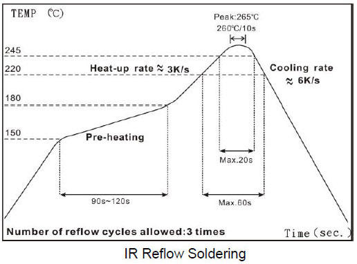
| Resistance to Soldering Heat | Solder Temperature: 260± 5°C Immersion Time: 10± 2 seconds | |
| Component Adhesion (Push Test) | 1 lbs. For 0402 2 lbs. For 0603 3 lbs. For the rest | The device should be soldered (260± 5°C for 10 seconds) to a tinned copper subs rate. A dynamiter force gauge should be applied to the side of the component. The device must with stand a minimum force of 2 or 4 pounds without a failure of adhesion on termination |
| Drop | No damage | Dropping chip by each side and each corner. Drop 10 times in total Drop height: 100 cm Drop weight: 125 g |
| Solderability | 90% covered with solder | Inductor shall be dipped in a melted solder bath at 245± 5°C for 3 seconds |
| Resistance to Solvent | No damage on appearance and marking | MIL-STD-202, Method 215 |
Climatic Test
| Item | Requirement | Item | ||||||||||||||
|---|---|---|---|---|---|---|---|---|---|---|---|---|---|---|---|---|
| Temperature Characteristic | Appearance: No damage L change: within ± 10% Q change: within ± 20% | -40°C ~ +125°C | ||||||||||||||
| Humidity | Temperature: 40± 2°C Relative Humidity: 90 ~ 95% Time: 96± 2 hrs Measured after exposure in the room condition for 2 hrs | |||||||||||||||
| Low Temperature Storage | Temperature: -40± 2°C Time: 96± 2 hrs Inductors are tested after 1 hour at room temperature | |||||||||||||||
| Thermal Shock | One cycle:
Total: 5 cycles | |||||||||||||||
| High Temperature Storage | Temperature: 125± 2°C Time: 96± 2 hrs Measured after exposure in the room condition for 1hour | |||||||||||||||
| High Temperature Load Life | There should be no evidence of short of open circuit. | Temperature: 85± 2°C Time: 1000± 12 hrs Load: Allowed DC current | ||||||||||||||
| Damp Heat with Load | Temperature: 40± 2°C Relative Humidity: 90 ~ 95% Time: 1000± 12 hrs Load: Allowed DC current |
☑ Storage Temperature: 15 ~ 28°C; Humidity < 80%RH
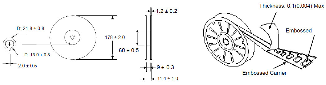
Reel Dimensions & Packaging Quantity (Unit : mm)
Paper Tape specification and Packaging Quantity (Unit : mm)
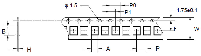
| Type | A | B | H | F | P | P0 | P1 | W | Reel (EA) |
|---|---|---|---|---|---|---|---|---|---|
| WL02 | 0.81 | 1.23 | 0.73 | 3.50 | 2.00 | 4.00 | 2.00 | 8.00 | 4,000 |
| WL03 | 1.35 | 1.95 | 0.95 | 3.50 | 4.00 | 4.00 | 2.00 | 8.00 | 4,000 |
Embossed Plastic Tape specification and Packaging Quantity (Unit : mm)
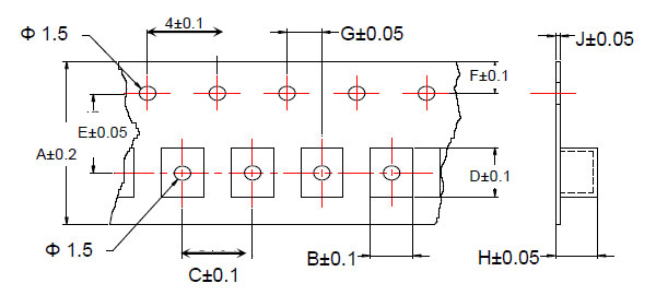
| Type | A | B | C | D | E | F | G | H | J | Reel (EA) |
|---|---|---|---|---|---|---|---|---|---|---|
| WL05 | 8 | 1.85 | 4 | 2.30 | 3.5 | 1.75 | 2 | 1.45 | 0.23 | 2,000 |
| WL05 (H) | 8 | 1.85 | 4 | 2.30 | 3.5 | 1.75 | 2 | 1.45 | 0.23 | 2,000 |
| WL08 | 8 | 2.70 | 4 | 2.80 | 3.5 | 1.75 | 2 | 2.00 | 0.23 | 2,000 |
| WL08 (H) | 8 | 2.70 | 4 | 2.80 | 3.5 | 1.75 | 2 | 2.00 | 0.23 | 2,000 |

Resistor de precisión de película delgada 0.01%, TC2ppm, con cable de unión, anticorrosivo, MELF. Detección...
Lee mas
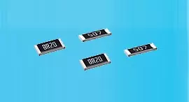
Inductores de chip de alta frecuencia cerámicos, tamaño pequeño hasta 01005. Película delgada, multicapa,...
Lee mas
El capacitor cerámico multicapa ofrece alta tensión, alta frecuencia, bajo ruido, alto Q, baja TCR....
Lee mas