

AUTOMOBILANWENDUNGEN
Dünnschicht-Präzisionswiderstand 0,01%, TC2ppm, Drahtbondable, Antikorrosiv, MELF. Stromsensoren, Metall,...
WeiterlesenMit Sitz in Taiwan ist Viking Tech Corporation seit 1997 einer der führenden Multilayer-Chip-Induktivität (CL-S-Serie CL02ST1N6-S) Hersteller.TS16949/ ISO9001/ ISO1400, erfüllen die AEC-Q200-Standards, und die Produkte werden für Anwendungen in der Automobil- und Elektronikindustrie verwendet.Viking bietet anti-Schwefel-, Anti-Überspannungs-, Puls-, Hochspannungs-, Hochleistungs-Präzisionswiderstände an, einschließlich Dünn-/Dickenfilmwiderständen, Automobilwiderständen, Melf-Widerständen und Strommesswiderständen.Geräuscharme, niedrige TC, Hochleistungsinduktivitäten wie RF-Induktivitäten, Chip-Induktivitäten, Leistungsinduktivitäten, variable Induktivitäten, Ferrit-Chip-Induktivitäten, geschirmte Induktivitäten, Drahtinduktivitäten und Tauchinduktivitäten.Viking bietet Kunden hochwertige Leistungswiderstände, Leistungsinduktivitäten und Aluminium-Elektrolytkondensatoren mit einem soliden Ruf an.Mit mehr als 20 Jahren Erfahrung ist Viking auf die Herstellung von Dünnschicht-Chipwiderständen, Chipwiderständen, Leistungsinduktivitäten, Strommesswiderständen, Dickschichtwiderständen, Chipkondensatoren und keramischen Substraten spezialisiert.
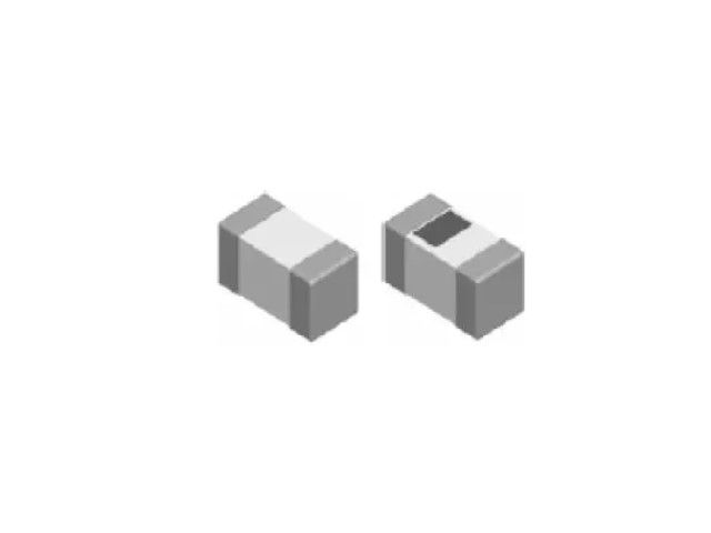
Mehrschicht-Keramik-Chip-Induktor, Hochfrequenz-, RF-Induktor für hohe SRF, ausgezeichnete Q, überlegbare Temperaturstabilität. Stabile Induktivität in Hochfrequenzschaltungen. Hochstabile Konstruktion für kritische Anforderungen.
CL Series0402 ±0.3nH 1.6nHμH 0.08 Ω 1000mA 8 6GHz
| Größe | Toleranz | Induktivität | Testbedingung | DCR (Ω) max. | IDC (mA) | Q | SRF |
|---|---|---|---|---|---|---|---|
| 0402 | ±0.3 | 1.6nH | 100MHz | 0.08 | 1000 | 8 | 6GHz |
CL01-S Multilayer Chip Inductors / High Q Type
| Inductance (nH) | Tolerance | Quality Factor min. |
Test Freq. (MHz) |
Test Voltage (mV) |
SRF (GHz) min. |
RDC (Ω) max. |
IDC (mA) max. |
|---|---|---|---|---|---|---|---|
| 0.6 | ± 0.1nH, ± 0.2nH, ± 0.3nH | 14 | 500 | 50 | 10.00 | 0.05 | 1000 |
| 0.7 | ± 0.1nH, ± 0.2nH, ± 0.3nH | 14 | 500 | 50 | 10.00 | 0.05 | 1000 |
| 0.8 | ± 0.1nH, ± 0.2nH, ± 0.3nH | 14 | 500 | 50 | 10.00 | 0.06 | 1000 |
| 0.9 | ± 0.1nH, ± 0.2nH, ± 0.3nH | 14 | 500 | 50 | 10.00 | 0.06 | 800 |
| 1.0 | ± 0.1nH, ± 0.2nH, ± 0.3nH | 14 | 500 | 50 | 10.00 | 0.07 | 800 |
| 1.1 | ± 0.1nH, ± 0.2nH, ± 0.3nH | 14 | 500 | 50 | 10.00 | 0.07 | 800 |
| 1.2 | ± 0.1nH, ± 0.2nH, ± 0.3nH | 14 | 500 | 50 | 10.00 | 0.10 | 800 |
| 1.3 | ± 0.1nH, ± 0.2nH, ± 0.3nH | 14 | 500 | 50 | 10.00 | 0.10 | 700 |
| 1.4 | ± 0.1nH, ± 0.2nH, ± 0.3nH | 14 | 500 | 50 | 10.00 | 0.10 | 700 |
| 1.5 | ± 0.1nH, ± 0.2nH, ± 0.3nH | 14 | 500 | 50 | 10.00 | 0.10 | 650 |
| 1.6 | ± 0.1nH, ± 0.2nH, ± 0.3nH | 14 | 500 | 50 | 10.00 | 0.10 | 650 |
| 1.7 | ± 0.1nH, ± 0.2nH, ± 0.3nH | 14 | 500 | 50 | 10.00 | 0.10 | 650 |
| 1.8 | ± 0.1nH, ± 0.2nH, ± 0.3nH | 14 | 500 | 50 | 9.00 | 0.15 | 650 |
| 2.0 | ± 0.1nH, ± 0.2nH, ± 0.3nH | 14 | 500 | 50 | 8.50 | 0.15 | 650 |
| 2.2 | ± 0.1nH, ± 0.2nH, ± 0.3nH | 14 | 500 | 50 | 7.50 | 0.15 | 650 |
| 2.4 | ± 0.1nH, ± 0.2nH, ± 0.3nH | 14 | 500 | 50 | 7.50 | 0.15 | 550 |
| 2.6 | ± 0.1nH, ± 0.2nH, ± 0.3nH | 14 | 500 | 50 | 7.50 | 0.20 | 550 |
| 2.7 | ± 0.1nH, ± 0.2nH, ± 0.3nH | 14 | 500 | 50 | 7.50 | 0.20 | 550 |
| 2.8 | ± 0.1nH, ± 0.2nH, ± 0.3nH | 14 | 500 | 50 | 7.50 | 0.20 | 500 |
| 3.0 | ± 0.1nH, ± 0.2nH, ± 0.3nH | 14 | 500 | 50 | 7.50 | 0.20 | 450 |
| 3.3 | ± 0.1nH, ± 0.2nH, ± 0.3nH | 14 | 500 | 50 | 7.50 | 0.25 | 450 |
| 3.6 | ± 0.1nH, ± 0.2nH, ± 0.3nH | 14 | 500 | 50 | 6.50 | 0.25 | 400 |
| 3.9 | ± 0.1nH, ± 0.2nH, ± 0.3nH | 14 | 500 | 50 | 6.50 | 0.25 | 400 |
| 4.3 | ± 0.1nH, ± 0.2nH, ± 0.3nH | 14 | 500 | 50 | 6.00 | 0.35 | 350 |
| 4.7 | ± 0.1nH, ± 0.2nH, ± 0.3nH | 14 | 500 | 50 | 6.00 | 0.40 | 350 |
| 5.1 | ± 0.1nH, ± 0.2nH, ± 0.3nH | 14 | 500 | 50 | 5.50 | 0.40 | 350 |
| 5.6 | ± 0.1nH, ± 0.2nH, ± 0.3nH | 14 | 500 | 50 | 5.00 | 0.40 | 350 |
| 6.2 | ± 0.1nH, ± 0.2nH, ± 0.3nH | 14 | 500 | 50 | 5.00 | 0.40 | 300 |
| 6.8 | ± 3%, ± 5% | 14 | 500 | 50 | 4.50 | 0.50 | 300 |
| 7.5 | ± 3%, ± 5% | 14 | 500 | 50 | 4.00 | 0.50 | 300 |
| 8.2 | ± 3%, ± 5% | 14 | 500 | 50 | 4.00 | 0.50 | 250 |
| 9.1 | ± 3%, ± 5% | 14 | 500 | 50 | 4.00 | 0.70 | 250 |
| 10 | ± 3%, ± 5% | 14 | 500 | 50 | 4.00 | 0.70 | 250 |
| 12 | ± 3%, ± 5% | 13 | 500 | 50 | 3.50 | 0.70 | 250 |
| 15 | ± 3%, ± 5% | 13 | 500 | 50 | 3.20 | 0.85 | 250 |
| 18 | ± 3%, ± 5% | 13 | 500 | 50 | 3.00 | 1.00 | 200 |
| 20 | ± 3%, ± 5% | 13 | 500 | 50 | 2.20 | 1.10 | 150 |
| 22 | ± 3%, ± 5% | 13 | 500 | 50 | 2.20 | 1.20 | 150 |
| 27 | ± 3%, ± 5% | 13 | 500 | 50 | 2.20 | 1.50 | 140 |
| 33 | ± 3%, ± 5% | 12 | 300 | 50 | 1.80 | 1.80 | 120 |
| 36 | ± 3%, ± 5% | 12 | 300 | 50 | 1.70 | 2.00 | 120 |
| 39 | ± 3%, ± 5% | 12 | 300 | 50 | 1.60 | 2.00 | 100 |
| 43 | ± 3%, ± 5% | 12 | 300 | 50 | 1.60 | 2.20 | 100 |
| 47 | ± 3%, ± 5% | 12 | 300 | 50 | 1.50 | 2.20 | 100 |
| 56 | ± 3%, ± 5% | 12 | 300 | 50 | 1.20 | 2.50 | 100 |
| 68 | ± 3%, ± 5% | 12 | 300 | 50 | 1.00 | 3.20 | 120 |
| 75 | ± 3%, ± 5% | 11 | 300 | 50 | 1.00 | 3.60 | 100 |
| 82 | ± 3%, ± 5% | 11 | 300 | 50 | 1.00 | 3.80 | 100 |
| 91 | ± 3%, ± 5% | 11 | 300 | 50 | 0.90 | 3.80 | 80 |
| 100 | ± 3%, ± 5% | 11 | 300 | 50 | 0.80 | 4.00 | 80 |
| 120 | ± 3%, ± 5% | 10 | 300 | 50 | 0.80 | 5.00 | 80 |
☑ Operating temperature range: -55 ~ +125°C
☑ L/Q Test equipment: E4991B + 16196a
☑ Test compensation: Short bar residual inductance 0.48nH
CL02-S01 Multilayer Chip Inductors / High Q Type
| Inductance (nH) | Tolerance | Quality Factor min. |
Test Freq. (MHz) |
Test Voltage (mV) |
SRF (MHz) min. |
RDC (Ω) max. |
IDC (mA) max. |
|---|---|---|---|---|---|---|---|
| 1.0 | ± 0.1nH | 13 | 500 | 50 | 6000 | 0.1 | 400 |
| 1.1 | ± 0.1nH | 13 | 500 | 50 | 6000 | 0.1 | 390 |
| 1.2 | ± 0.1nH | 13 | 500 | 50 | 600 | 0.1 | 390 |
| 1.3 | ± 0.1nH | 13 | 500 | 50 | 6000 | 0.2 | 280 |
| 1.4 | ± 0.1nH | 13 | 500 | 50 | 6000 | 0.2 | 280 |
| 1.5 | ± 0.1nH | 13 | 500 | 50 | 6000 | 0.2 | 280 |
| 1.6 | ± 0.1nH | 13 | 500 | 50 | 6000 | 0.3 | 220 |
| 1.7 | ± 0.1nH | 13 | 500 | 50 | 6000 | 0.3 | 280 |
| 1.8 | ± 0.1nH | 13 | 500 | 50 | 6000 | 0.3 | 280 |
| 1.9 | ± 0.1nH | 13 | 500 | 50 | 6000 | 0.3 | 220 |
| 2.0 | ± 0.1nH | 13 | 500 | 50 | 6000 | 0.3 | 220 |
| 2.1 | ± 0.1nH | 13 | 500 | 50 | 6000 | 0.3 | 220 |
| 2.2 | ± 0.1nH | 13 | 500 | 50 | 6000 | 0.3 | 220 |
| 2.3 | ± 0.1nH | 13 | 500 | 50 | 6000 | 0.3 | 220 |
| 2.4 | ± 0.1nH | 13 | 500 | 50 | 6000 | 0.3 | 220 |
| 2.5 | ± 0.1nH | 13 | 500 | 50 | 6000 | 0.3 | 220 |
| 2.6 | ± 0.1nH | 13 | 500 | 50 | 6000 | 0.3 | 220 |
| 2.7 | ± 0.1nH | 13 | 500 | 50 | 6000 | 0.3 | 220 |
| 2.8 | ± 0.1nH | 13 | 500 | 50 | 6000 | 0.4 | 190 |
| 2.9 | ± 0.1nH | 13 | 500 | 50 | 6000 | 0.4 | 190 |
| 3.0 | ± 0.1nH | 13 | 500 | 50 | 6000 | 0.4 | 190 |
| 3.1 | ± 0.1nH | 13 | 500 | 50 | 6000 | 0.4 | 190 |
| 3.2 | ± 0.1nH | 13 | 500 | 50 | 6000 | 0.4 | 190 |
| 3.3 | ± 0.1nH | 13 | 500 | 50 | 6000 | 0.5 | 190 |
| 3.4 | ± 0.1nH | 13 | 500 | 50 | 6000 | 0.5 | 190 |
| 3.5 | ± 0.1nH | 13 | 500 | 50 | 6000 | 0.5 | 190 |
| 3.6 | ± 0.1nH | 13 | 500 | 50 | 6000 | 0.5 | 190 |
| 3.7 | ± 0.1nH | 13 | 500 | 50 | 6000 | 0.5 | 190 |
| 3.8 | ± 0.1nH | 13 | 500 | 50 | 6000 | 0.5 | 170 |
| 3.9 | ± 0.1nH | 13 | 500 | 50 | 6000 | 0.4 | 170 |
| 4.3 | ± 0.1nH | 13 | 500 | 50 | 6000 | 0.6 | 160 |
| 4.7 | ± 0.1nH | 13 | 500 | 50 | 6000 | 0.6 | 160 |
| 5.1 | ± 0.1nH | 13 | 500 | 50 | 6000 | 0.7 | 140 |
| 5.6 | ± 0.1nH | 13 | 500 | 50 | 6000 | 0.7 | 140 |
| 6.2 | ± 0.1nH | 13 | 500 | 50 | 6000 | 0.9 | 130 |
| 6.8 | ± 0.1nH | 13 | 500 | 50 | 6000 | 0.9 | 130 |
| 7.5 | ± 0.1nH | 13 | 500 | 50 | 5500 | 1.1 | 110 |
| 8.2 | ± 0.1nH | 13 | 500 | 50 | 5500 | 1.1 | 110 |
| 9.1 | ± 0.1nH | 13 | 500 | 50 | 4500 | 1.3 | 100 |
| 10 | ± 2% | 13 | 500 | 50 | 4500 | 1.3 | 100 |
| 12 | ± 2% | 13 | 500 | 50 | 3700 | 1.6 | 90 |
| 15 | ± 2% | 13 | 500 | 50 | 3300 | 1.8 | 90 |
| 18 | ± 2% | 13 | 500 | 50 | 3100 | 2.0 | 80 |
| 22 | ± 2% | 13 | 500 | 50 | 2800 | 2.6 | 70 |
| 27 | ± 2% | 13 | 500 | 50 | 2500 | 3.8 | 60 |
| 33 | ± 2% | 13 | 500 | 50 | 2100 | 3.8 | 60 |
☑ Operating temperature range: -40 ~ +85°C
☑ Keysight E4991B+Testing fixture 16197A.Short bar residual inductance=0.556nH
CL02-S02 Multilayer Chip Inductors / High Q Type
| Inductance (nH) | Tolerance | L Test Freq. (MHz) |
Quality min. |
Q Test Freq. (MHz) |
Test Voltage (mV) |
SRF (MHz) min. |
RDC (Ω) max. |
IDC (mA) max. |
|---|---|---|---|---|---|---|---|---|
| 0.6 | ± 0.1nH, ± 0.2nH, ± 0.3nH | 100 | - | 250 | 50 | 15000 | 0.01 | 1200 |
| 0.7 | ± 0.1nH, ± 0.2nH, ± 0.3nH | 100 | - | 250 | 50 | 15000 | 0.02 | 1200 |
| 0.8 | ± 0.1nH, ± 0.2nH, ± 0.3nH | 100 | - | 250 | 50 | 15000 | 0.02 | 1200 |
| 0.9 | ± 0.1nH, ± 0.2nH, ± 0.3nH | 100 | - | 250 | 50 | 15000 | 0.03 | 1200 |
| 1.0 | ± 0.1nH, ± 0.2nH, ± 0.3nH | 100 | 23 | 250 | 50 | 15000 | 0.03 | 1200 |
| 1.1 | ± 0.1nH, ± 0.2nH, ± 0.3nH | 100 | 23 | 250 | 50 | 14000 | 0.03 | 1200 |
| 1.2 | ± 0.1nH, ± 0.2nH, ± 0.3nH | 100 | 23 | 250 | 50 | 13000 | 0.03 | 1200 |
| 1.3 | ± 0.1nH, ± 0.2nH, ± 0.3nH | 100 | 23 | 250 | 50 | 12000 | 0.03 | 1200 |
| 1.4 | ± 0.1nH, ± 0.2nH, ± 0.3nH | 100 | 12 | 250 | 50 | 13000 | 0.04 | 1200 |
| 1.5 | ± 0.1nH, ± 0.2nH, ± 0.3nH | 100 | 23 | 250 | 50 | 11000 | 0.04 | 1000 |
| 1.6 | ± 0.1nH, ± 0.2nH, ± 0.3nH | 100 | 23 | 250 | 50 | 10000 | 0.04 | 1000 |
| 1.7 | ± 0.1nH, ± 0.2nH, ± 0.3nH | 100 | 23 | 250 | 50 | 10000 | 0.04 | 1000 |
| 1.8 | ± 0.1nH, ± 0.2nH, ± 0.3nH | 100 | 23 | 250 | 50 | 9000 | 0.04 | 1000 |
| 1.9 | ± 0.1nH, ± 0.2nH, ± 0.3nH | 100 | 23 | 250 | 50 | 8000 | 0.05 | 1000 |
| 2.0 | ± 0.1nH, ± 0.2nH, ± 0.3nH | 100 | 23 | 250 | 50 | 8000 | 0.05 | 1000 |
| 2.1 | ± 0.1nH, ± 0.2nH, ± 0.3nH | 100 | 23 | 250 | 50 | 8000 | 0.06 | 1000 |
| 2.2 | ± 0.1nH, ± 0.2nH, ± 0.3nH | 100 | 23 | 250 | 50 | 8000 | 0.06 | 1000 |
| 2.3 | ± 0.1nH, ± 0.2nH, ± 0.3nH | 100 | 23 | 250 | 50 | 7000 | 0.07 | 1000 |
| 2.4 | ± 0.1nH, ± 0.2nH, ± 0.3nH | 100 | 23 | 250 | 50 | 6500 | 0.07 | 1000 |
| 2.5 | ± 0.1nH, ± 0.2nH, ± 0.3nH | 100 | 23 | 250 | 50 | 6500 | 0.06 | 900 |
| 2.6 | ± 0.1nH, ± 0.2nH, ± 0.3nH | 100 | 23 | 250 | 50 | 6500 | 0.07 | 900 |
| 2.7 | ± 0.1nH, ± 0.2nH, ± 0.3nH | 100 | 23 | 250 | 50 | 6500 | 0.07 | 900 |
| 2.8 | ± 0.1nH, ± 0.2nH, ± 0.3nH | 100 | 23 | 250 | 50 | 6500 | 0.07 | 900 |
| 2.9 | ± 0.1nH, ± 0.2nH, ± 0.3nH | 100 | 23 | 250 | 50 | 6500 | 0.08 | 900 |
| 3.0 | ± 0.1nH, ± 0.2nH, ± 0.3nH | 100 | 23 | 250 | 50 | 6000 | 0.09 | 900 |
| 3.1 | ± 0.1nH, ± 0.2nH, ± 0.3nH | 100 | 23 | 250 | 50 | 6000 | 0.09 | 900 |
| 3.2 | ± 0.1nH, ± 0.2nH, ± 0.3nH | 100 | 23 | 250 | 50 | 6000 | 0.09 | 900 |
| 3.3 | ± 0.1nH, ± 0.2nH, ± 0.3nH | 100 | 23 | 250 | 50 | 6000 | 0.08 | 900 |
| 3.4 | ± 0.1nH, ± 0.2nH, ± 0.3nH | 100 | 23 | 250 | 50 | 6000 | 0.09 | 900 |
| 3.5 | ± 0.1nH, ± 0.2nH, ± 0.3nH | 100 | 23 | 250 | 50 | 5800 | 0.09 | 900 |
| 3.6 | ± 0.1nH, ± 0.2nH, ± 0.3nH | 100 | 23 | 250 | 50 | 5500 | 0.09 | 900 |
| 3.7 | ± 0.1nH, ± 0.2nH, ± 0.3nH | 100 | 23 | 250 | 50 | 5500 | 0.10 | 900 |
| 3.8 | ± 0.1nH, ± 0.2nH, ± 0.3nH | 100 | 23 | 250 | 50 | 5000 | 0.10 | 900 |
| 3.9 | ± 0.1nH, ± 0.2nH, ± 0.3nH | 100 | 23 | 250 | 50 | 5000 | 0.09 | 800 |
| 4.1 | ± 0.1nH, ± 0.2nH, ± 0.3nH | 100 | 23 | 250 | 50 | 5000 | 0.10 | 800 |
| 4.3 | ± 0.1nH, ± 0.2nH, ± 0.3nH | 100 | 23 | 250 | 50 | 5000 | 0.10 | 800 |
| 4.7 | ± 0.1nH, ± 0.2nH, ± 0.3nH | 100 | 23 | 250 | 50 | 5000 | 0.11 | 800 |
| 4.9 | ± 0.1nH, ± 0.2nH, ± 0.3nH | 100 | 23 | 250 | 50 | 5000 | 0.11 | 800 |
| 5.1 | ± 0.1nH, ± 0.2nH, ± 0.3nH | 100 | 23 | 250 | 50 | 4500 | 0.12 | 800 |
| 5.4 | ± 0.1nH, ± 0.2nH, ± 0.3nH | 100 | 23 | 250 | 50 | 4500 | 0.13 | 800 |
| 5.6 | ± 0.1nH, ± 0.2nH, ± 0.3nH | 100 | 23 | 250 | 50 | 4500 | 0.13 | 800 |
| 5.8 | ± 0.1nH, ± 0.2nH, ± 0.3nH | 100 | 23 | 250 | 50 | 4000 | 0.13 | 700 |
| 6.0 | ± 0.1nH, ± 0.2nH, ± 0.3nH | 100 | 23 | 250 | 50 | 4000 | 0.13 | 700 |
| 6.2 | ± 0.1nH, ± 0.2nH, ± 0.3nH | 100 | 23 | 250 | 50 | 4000 | 0.13 | 700 |
| 6.5 | ± 2%, ± 3%, ± 5% | 100 | 23 | 250 | 50 | 4000 | 0.14 | 700 |
| 6.8 | ± 2%, ± 3%, ± 5% | 100 | 23 | 250 | 50 | 4000 | 0.14 | 700 |
| 7.3 | ± 2%, ± 3%, ± 5% | 100 | 23 | 250 | 50 | 4000 | 0.16 | 600 |
| 7.5 | ± 2%, ± 3%, ± 5% | 100 | 23 | 250 | 50 | 4000 | 0.16 | 600 |
| 8.2 | ± 2%, ± 3%, ± 5% | 100 | 23 | 250 | 50 | 3600 | 0.16 | 550 |
| 8.7 | ± 2%, ± 3%, ± 5% | 100 | 23 | 250 | 50 | 3500 | 0.17 | 550 |
| 9.1 | ± 2%, ± 3%, ± 5% | 100 | 23 | 250 | 50 | 3400 | 0.17 | 550 |
| 9.5 | ± 2%, ± 3%, ± 5% | 100 | 23 | 250 | 50 | 3300 | 0.21 | 500 |
| 10 | ± 2%, ± 3%, ± 5% | 100 | 23 | 250 | 50 | 3300 | 0.19 | 500 |
| 11 | ± 2%, ± 3%, ± 5% | 100 | 23 | 250 | 50 | 3000 | 0.22 | 450 |
| 12 | ± 2%, ± 3%, ± 5% | 100 | 23 | 250 | 50 | 2800 | 0.24 | 450 |
| 13 | ± 2%, ± 3%, ± 5% | 100 | 23 | 250 | 50 | 2800 | 0.26 | 400 |
| 15 | ± 2%, ± 3%, ± 5% | 100 | 23 | 250 | 50 | 2300 | 0.28 | 400 |
☑ Operating temperature range: -55 ~ +125°C
☑ L/Q test equipment: Keysight E4991B+Testing fixture 16197A.Short bar residual inductance=0.556nH
CL02-S Multilayer Chip Inductors / High Frequency Type
| Inductance (nH) | Tolerance | Quality Factor /min. | L/Q Freq. (MHz) | Q (Typical) Freq. (MHz) | SRF min. (GHz) | RDC (Ω) max. | IDC (mA) max. | |||||
|---|---|---|---|---|---|---|---|---|---|---|---|---|
| 100 | 300 | 500 | 800 | 1000 | 1800 | |||||||
| 1.0 | ± 0.3nH | 5 | 100 | 9 | 16 | 20 | 25 | 28 | 31 | >8.50 | 0.10 | 500 |
| 1.2 | ± 0.3nH | 5 | 100 | 9 | 15 | 18 | 24 | 27 | 31 | >8.50 | 0.12 | 500 |
| 1.5 | ± 0.3nH | 5 | 100 | 7 | 12 | 16 | 20 | 21 | 29 | >8.50 | 0.15 | 500 |
| 1.8 | ± 0.3nH | 5 | 100 | 7 | 12 | 16 | 20 | 21 | 29 | >8.50 | 0.17 | 500 |
| 2.2 | ± 0.3nH | 5 | 100 | 7 | 12 | 16 | 20 | 21 | 30 | >8.50 | 0.17 | 500 |
| 2.7 | ± 0.3nH | 5 | 100 | 7 | 12 | 16 | 20 | 21 | 29 | >8.50 | 0.20 | 500 |
| 3.3 | ± 0.3nH | 5 | 100 | 7 | 12 | 15 | 19 | 20 | 27 | >8.50 | 0.22 | 400 |
| 3.9 | ± 0.3nH | 5 | 100 | 7 | 12 | 15 | 20 | 21 | 28 | 7.50 | 0.25 | 400 |
| 4.7 | ± 0.3nH | 5 | 100 | 7 | 12 | 15 | 19 | 20 | 27 | 6.50 | 0.28 | 400 |
| 5.6 | ± 0.3nH | 5 | 100 | 8 | 12 | 15 | 20 | 22 | 30 | 6.50 | 0.30 | 400 |
| 6.8 | ± 5%, ± 10% | 5 | 100 | 8 | 12 | 15 | 20 | 22 | 30 | 6.50 | 0.35 | 400 |
| 8.2 | ± 5%, ± 10% | 5 | 100 | 8 | 12 | 15 | 19 | 21 | 30 | 6.50 | 0.38 | 350 |
| 10 | ± 5%, ± 10% | 5 | 100 | 8 | 13 | 16 | 21 | 23 | 32 | 4.70 | 0.42 | 350 |
| 12 | ± 5%, ± 10% | 5 | 100 | 8 | 13 | 16 | 20 | 23 | 27 | 4.30 | 0.47 | 350 |
| 15 | ± 5%, ± 10% | 5 | 100 | 8 | 12 | 15 | 19 | 22 | 28 | 4.00 | 0.50 | 300 |
| 18 | ± 5%, ± 10% | 5 | 100 | 8 | 13 | 16 | 21 | 24 | 32 | 4.00 | 0.60 | 250 |
| 22 | ± 5%, ± 10% | 5 | 100 | 8 | 13 | 17 | 22 | 26 | 31 | 3.50 | 0.70 | 200 |
| 27 | ± 5%, ± 10% | 5 | 100 | 8 | 14 | 18 | 23 | 26 | 32 | 3.00 | 0.80 | 200 |
| 33 | ± 5%, ± 10% | 5 | 100 | 8 | 14 | 17 | 23 | 27 | 32 | 2.50 | 0.90 | 200 |
| 39 | ± 5%, ± 10% | 5 | 100 | 8 | 14 | 18 | 23 | 27 | 32 | 2.00 | 1.00 | 200 |
| 47 | ± 5%, ± 10% | 7 | 100 | 9 | 14 | 18 | 22 | 24 | 29 | 2.40 | 2.20 | 100 |
| 56 | ± 5%, ± 10% | 7 | 100 | 9 | 14 | 18 | 23 | 24 | 29 | 2.30 | 2.50 | 100 |
| 68 | ± 5%, ± 10% | 7 | 100 | 9 | 14 | 17 | 22 | 24 | 29 | 2.20 | 2.70 | 100 |
| 82 | ± 5%, ± 10% | 7 | 100 | 8 | 13 | 17 | 20 | 20 | 16 | 2.10 | 2.90 | 100 |
| 100 | ± 5%, ± 10% | 7 | 100 | 8 | 13 | 17 | 20 | 20 | 13 | 2.00 | 3.20 | 100 |
☑ Operating temperature range: -55~+125°C
CL03-S Multilayer Chip Inductors / High Frequency Type
| Inductance (nH) | Tolerance | Quality Factor /min. | L/Q Freq. (MHz) | Q (Typical) Freq. (MHz) | SRF min. (GHz) | RDC (Ω) max. | IDC (mA) max. | |||||
|---|---|---|---|---|---|---|---|---|---|---|---|---|
| 100 | 300 | 500 | 800 | 1000 | 1800 | |||||||
| 10 | ± 5% | 8 | 100 | 10 | 22 | 28 | 35 | 39 | 45 | >6.00 | 0.6 | 500 |
| 12 | ± 5% | 8 | 100 | 10 | 18 | 23 | 26 | 32 | 42 | 6.00 | 0.7 | 500 |
| 15 | ± 5% | 8 | 100 | 12 | 22 | 28 | 35 | 39 | 42 | 5.50 | 0.8 | 500 |
| 18 | ± 5% | 8 | 100 | 10 | 18 | 22 | 25 | 30 | 43 | 5.20 | 0.9 | 300 |
| 22 | ± 5% | 8 | 100 | 12 | 21 | 27 | 34 | 37 | 37 | 5.00 | 1.0 | 300 |
| 27 | ± 5% | 8 | 100 | 10 | 18 | 24 | 26 | 32 | 38 | 4.80 | 1.2 | 300 |
| 33 | ± 5% | 8 | 100 | 12 | 21 | 27 | 33 | 35 | 31 | 4.50 | 1.4 | 300 |
| 39 | ± 5% | 8 | 100 | 11 | 20 | 26 | 32 | 34 | 29 | 4.00 | 1.5 | 200 |
| 47 | ± 5% | 8 | 100 | 12 | 20 | 26 | 31 | 34 | 27 | 3.50 | 1.6 | 200 |
| 56 | ± 5% | 8 | 100 | 11 | 20 | 26 | 31 | 34 | 24 | 3.00 | 1.8 | 200 |
| 68 | ± 5% | 8 | 100 | 10 | 18 | 21 | 24 | 28 | 20 | 2.80 | 2.0 | 200 |
| 82 | ± 5% | 8 | 100 | 10 | 19 | 22 | 26 | 26 | 15 | 2.50 | 2.2 | 200 |
| 100 | ± 5% | 8 | 100 | 10 | 19 | 24 | 27 | 25 | - | 2.00 | 2.5 | 150 |
| 120 | ± 5% | 8 | 100 | 10 | 19 | 23 | 26 | 24 | - | 1.60 | 2.8 | 150 |
| 150 | ± 5% | 8 | 100 | 10 | 18 | 24 | 26 | 23 | - | 1.40 | 3.0 | 150 |
| 180 | ± 5% | 8 | 100 | 10 | 17 | 22 | 23 | - | - | 1.00 | 3.4 | 150 |
☑ Operating temperature range: -40~+85°C
Electrical Performance Test
| Item | Requirement | Test Condition |
|---|---|---|
| Inductance | In Within specified tolerance | Temperature: 20 ± 1°C Relative Humidity: 45 to 85%RH Atmospheric Pressure: 86 to 106kpa Measuring equipment and fixture: 0201: E991A+HP16197A 0402/0603: E991A + HP16192A Test Signal: -20dBm or 50mV Test compensation(for 0201 high Q): Product true value = test value + compensation value. for L < 3.6nH, compensation value is 0.25nH; for 3.6nH ≤ L<6.8nH, compensation value is 0.43nH; for 6.8 nH ≤ L<9.1nH, compensation value is 0.5nH; for 9.1 nH ≤ L<33nH, compensation value is 0.85nH; for L ≥ 33nH, compensation value is 0.85nH; |
| Q Value | In accordance with electrical specification | Temperature: 20 ± 1°C Relative Humidity: 45 to 85%RH Atmospheric Pressure: 86 to 106kpa |
| DC Resistance | In accordance with electrical specification | Temperature: 20 ± 1°C Relative Humidity: 45 to 85%RH Atmospheric Pressure: 86 to 106kpa Measuring equipment: HP 4338 |
Mechanical Characteristies Test
| Item | Requirement | Test Condition |
|---|---|---|
| Bending Strength | No mechanical damage shall be observed | Flexure: 2mm Pressurizing speed: 0.5mm/sec Keep time: 30sec 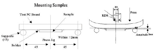 |
| Solderability | No visible mechanical damage Wetting shall exceed 75% coverage for 0201 series; exceed 95% coverage for others |
Solder temperature: 240 ± 2°C Time: 3 seconds Solder: Sn/3.0Ag/0.5Cu Flux: 25% resin and 75% ethanol in weight |
| Resistance to Soldering Heat | No visible mechanical damage Wetting shall exceed 75% coverage for 0201 series; exceed 95% coverage for others Inductance change: within ± 10% Q change: within ± 20% |
Solder temperature: 260 ± 3°C Time: 5 seconds Solder: Sn/3.0Ag/0.5Cu Flux: 25% resin and 75% ethanol in weight The chip shall be stabilized at normal condition for 1~2 hours before measuring |
| Dropping | No visible mechanical damage Inductance change: within ± 10% Q change: within ± 20% |
Drop chip inductor 10 times on a concrete floor form a height of 100cm |
Climatic Test
| Item | Requirement | Test Condition |
|---|---|---|
| Thermal Shock | No visible damage Inductance variation within 10% Q variation within 20% |
0201/0402 series: -55°C for 30 ± 3 min→125°C for 30 ± 3 min 0603 series: -40°C for 30 ± 3 min→85°C for 30 ± 3 min Transforming interval: max. 20 seconds Test cycle: 100 cycles The chip shall be stabilized at normal condition for 1~2 hours Before measuring |
| Resistance to Low Temperature | Temperature: 0201/0402 series: -55 ± 2°C; 0603 series: -40 ± 2°C Time: 1000 ± 24 hours The chip shall be stabilized at normal condition for 1~2 hours Before measuring |
|
| Resistance to High Temperature | Temperature: 0201/0402 series: 125 ± 2°C; 0603 series: 85 ± 2°C Time: 1000 ± 24 hours The chip shall be stabilized at normal condition for 1~2 hours Before measuring |
|
| Damp Heat (Steady States) | Temperature: 60 ± 2°C Humidity: 90 ~ 95% RH. Time: 1000 ± 24 hours The chip shall be stabilized at normal condition for 1~2 hours Before measuring |
|
| Loading Under Damp Heat | Temperature: 60 ± 2°C Humidity: 90~95% RH. Time: 1000 ± 24 hours Applied current: Rated current The chip shall be stabilized at normal condition for 1~2 hours Before measuring |
|
| Loading at High Temperature (Life Test) | Temperature: 0201/0402 series: 125 ± 2°C; 0603 series: 85 ± 2°C Time: 1000 ± 24 hours Applied current: Rated current The chip shall be stabilized at normal condition for 1~2 hours Before measuring |
☑ Storage Temperature: 15 ~ 28°C; Humidity < 80%RH
Reel Dimension (Unit : mm)
| Type | A | B | C | W | T | Quantity (EA) | 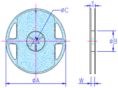 |
|---|---|---|---|---|---|---|---|
| CLE5-S | 178 ± 2 | 50 or more | 13.0 ± 0.20 | 8.4 +1.5/-0 | 14.4 max | 20,000 | |
| CL01-S | 178 ± 1 | 60.0 ± 0.5 | 13.0 ± 0.20 | 9.00 ± 0.5 | 12.0 ± 0.15 | 15,000 | |
| CL02-S | 178 ± 1 | 57.0 ± 2 | 12.5 ± 1.50 | 8.00 +1.5/-0 | 12.0 ± 0.15 | 10,000 | |
| CL03-S | 178 ± 1 | 60.0 ± 0.5 | 13.0 ± 0.20 | 9.00 ± 0.5 | 12.0 ± 0.15 | 4,000 |
Tape Specifications (Unit : mm)
| Type | A | B | T | W | P | F | K | Tape | 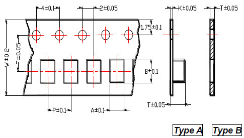 |
|---|---|---|---|---|---|---|---|---|---|
| CLE5-S | 0.25 ± 0.03 | 0.46 ± 0.03 | 0.31 ± 0.03 | 8 | 2 | 3.5 | - | B | |
| CL01-S | 0.40 | 0.70 | 0.50 | 8 | 2 | 3.5 | - | B | |
| CL02-S | 0.65 | 1.15 | 0.80 | 8 | 2 | 3.5 | - | B | |
| CL03-S | 1.10 | 1.80 | 1.10 | 8 | 4 | 3.5 | - | B |

Dünnschicht-Präzisionswiderstand 0,01%, TC2ppm, Drahtbondable, Antikorrosiv, MELF. Stromsensoren, Metall,...
Weiterlesen
Keramische Hochfrequenz-Chip-Induktoren, klein bis 01005. Dünnschicht-, Mehrschicht-, Drahtgewickelte-,...
Weiterlesen
Multilayer-Keramikkondensatoren bieten hohe Spannung, hohe Frequenz, niedrigen Geräuschpegel, hohe Q, niedrigen...
Weiterlesen