
APPLICATIONS AUTOMOBILES
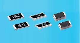
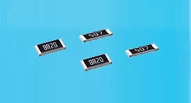
Résistance de précision en film mince 0,01 %, TC2ppm, wirebondale, anti-corrosion, MELF. Détection...
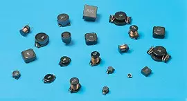
Lire la suiteBasée à Taïwan, Viking Tech Corporation est l'un des principaux fabricants de Inducteur à fil enroulé (Ferrite) (Série NL NL05JT1R5) depuis 1997.TS16949/ ISO9001/ ISO1400, répondent aux normes AEC-Q200, et les produits sont utilisés pour des applications automobiles et d'appareils électroniques.Viking fournit des résistances de précision anti-soufre, anti-surtension, à impulsion, haute tension, haute puissance, y compris des résistances à film mince/épais, des résistances automobiles, des résistances melf, des résistances de détection de courant.Inducteurs à faible bruit, faible TC et haute puissance tels que les inducteurs RF, inducteurs de puce, inducteurs de puissance, inducteurs variables, inducteurs de puce en ferrite, inducteurs blindés, inducteurs en fil enroulé et inducteurs à immersion.Viking a offert aux clients des résistances de puissance, des inducteurs de puissance et des condensateurs électrolytiques en aluminium de haute qualité avec une solide réputation.Avec plus de 20 ans d'expérience, Viking est spécialisé dans la fabrication de résistances à film mince, résistances de puce, inducteurs de puissance, résistances de détection de courant, résistances à film épais, condensateurs de puce et substrats en céramique.
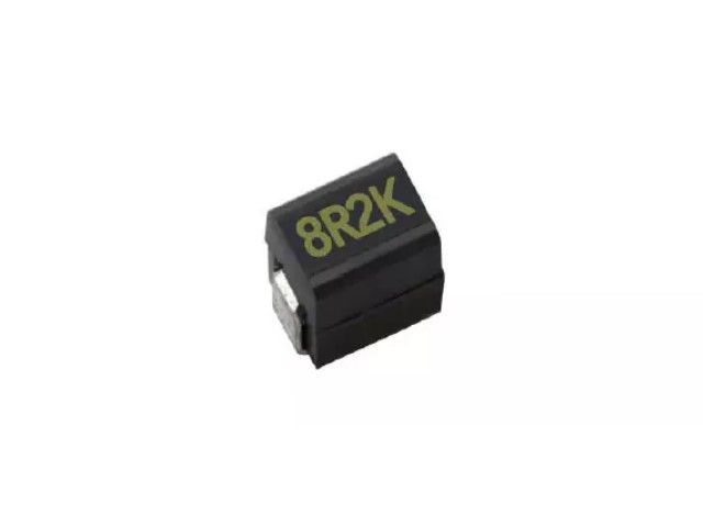
Inducteur en ferrite à puce enroulé de fil, courant élevé, type moulé et ouvert disponibles. Taille réduite jusqu'à 0603, très bonne soudabilité par soudure à la vague ou fer à souder. Très résistant aux chocs mécaniques et à la pression. Très fiable dans des environnements de changements de température soudains et d'humidité. Caractéristiques super Q.
NL Series0805 ±5% 1.5μH 1 Ω 720mA 15 400
| Taille | Tolérance | Inductance | Conditions d'essai | DCR (Ω) max. | IDC (mA) | Q | SRF |
|---|---|---|---|---|---|---|---|
| 0805 | ±5% | 1.5 | 7.9MHz | 1 | 720 | 15 | 400 |
NL03 Wound Chip Inductors (Ferrite / Open Type) / Large Current Type
| Codes | Inductance (uH) | Tolerance | Q min. | Test Freq. (MHz) | SRF (MHz) min. | DCR (Ω) max. | IDC (mA) max. | Color Code |
|---|---|---|---|---|---|---|---|---|
| R10 | 0.10 | ± 5, ± 10, ± 20% | 12 | 7.9 | 1150 | 0.13 | 1700 | Black |
| R12 | 0.12 | ± 5, ± 10, ± 20% | 12 | 7.9 | 1100 | 0.15 | 1700 | Orange |
| R15 | 0.15 | ± 5, ± 10, ± 20% | 15 | 7.9 | 1050 | 0.15 | 1600 | Brown |
| R18 | 0.18 | ± 5, ± 10, ± 20% | 15 | 7.9 | 950 | 0.15 | 1500 | Green |
| R22 | 0.22 | ± 5, ± 10, ± 20% | 15 | 7.9 | 900 | 0.30 | 1200 | Red |
| R24 | 0.24 | ± 5, ± 10, ± 20% | 15 | 7.9 | 850 | 0.16 | 1460 | Green |
| R27 | 0.27 | ± 5, ± 10, ± 20% | 15 | 7.9 | 835 | 0.30 | 1460 | Yellow |
| R33 | 0.33 | ± 5, ± 10, ± 20% | 15 | 7.9 | 725 | 0.40 | 1420 | Orange |
| R39 | 0.39 | ± 5, ± 10, ± 20% | 15 | 7.9 | 680 | 0.41 | 1400 | Blue |
| R47 | 0.47 | ± 5, ± 10, ± 20% | 15 | 7.9 | 640 | 0.43 | 1400 | Black |
| R56 | 0.56 | ± 5, ± 10, ± 20% | 15 | 7.9 | 630 | 0.44 | 1400 | Brown |
| R68 | 0.68 | ± 5, ± 10, ± 20% | 15 | 7.9 | 510 | 0.52 | 1340 | Red |
| R78 | 0.78 | ± 5, ± 10, ± 20% | 15 | 7.9 | 465 | 0.63 | 1300 | Orange |
| R82 | 0.82 | ± 5, ± 10, ± 20% | 15 | 7.9 | 460 | 0.69 | 1200 | Yellow |
| 1R0 | 1.0 | ± 5, ± 10, ± 20% | 15 | 7.9 | 320 | 0.81 | 1100 | Green |
| 1R2 | 1.2 | ± 5, ± 10, ± 20% | 15 | 7.9 | 270 | 0.87 | 1100 | Blue |
| 1R5 | 1.5 | ± 5, ± 10, ± 20% | 15 | 7.9 | 230 | 0.96 | 920 | Violet |
| 1R8 | 1.8 | ± 5, ± 10, ± 20% | 15 | 7.9 | 210 | 1.10 | 900 | Gray |
| 2R2 | 2.2 | ± 5, ± 10, ± 20% | 15 | 7.9 | 115 | 1.20 | 740 | White |
| 2R7 | 2.7 | ± 5, ± 10, ± 20% | 15 | 7.9 | 100 | 1.38 | 700 | Black |
| 3R3 | 3.3 | ± 5, ± 10, ± 20% | 15 | 7.9 | 84 | 1.50 | 680 | Brown |
| 3R9 | 3.9 | ± 5, ± 10, ± 20% | 15 | 7.9 | 75 | 1.50 | 600 | Red |
| 4R7 | 4.7 | ± 5, ± 10, ± 20% | 15 | 7.9 | 67 | 2.10 | 580 | Orange |
| 5R6 | 5.6 | ± 5, ± 10, ± 20% | 15 | 7.9 | 55 | 2.37 | 540 | Yellow |
| 6R8 | 6.8 | ± 5, ± 10, ± 20% | 15 | 7.9 | 48 | 3.10 | 500 | Green |
| 7R8 | 7.8 | ± 5, ± 10, ± 20% | 15 | 7.9 | 40 | 3.35 | 460 | Blue |
| 8R2 | 8.2 | ± 5, ± 10, ± 20% | 15 | 7.9 | 38 | 3.50 | 440 | Violet |
| 100 | 10 | ± 5, ± 10, ± 20% | 15 | 7.9 | 32 | 4.46 | 400 | Gray |
NL05 Wire Wound Chip Inductors (Ferrite / Open Type) / Large Current Type
| Codes | Inductance (uH) | Tolerance | Q typ. | Test Freq. (MHz) | SRF (MHz) typ. | DCR (Ω) max. | IDC (mA) typ. | Color Code |
|---|---|---|---|---|---|---|---|---|
| R47 | 0.47 | ± 5, ± 10, ± 20% | 14 | 7.9 | 850 | 0.156 | 1400 | Blue |
| R68 | 0.68 | ± 5, ± 10, ± 20% | 14 | 7.9 | 765 | 0.195 | 1200 | Gray |
| 1R0 | 1.00 | ± 5, ± 10, ± 20% | 14 | 7.9 | 208 | 0.169 | 1100 | Black |
| 1R2 | 1.20 | ± 5, ± 10, ± 20% | 14 | 7.9 | 159 | 0.208 | 960 | Red |
| 1R5 | 1.50 | ± 5, ± 10, ± 20% | 14 | 7.9 | 159 | 0.221 | 920 | Brown |
| 1R8 | 1.80 | ± 5, ± 10, ± 20% | 14 | 7.9 | 112 | 0.260 | 860 | Orange |
| 2R2 | 2.20 | ± 5, ± 10, ± 20% | 13 | 7.9 | 87 | 0.286 | 740 | Red |
| 2R7 | 2.70 | ± 5, ± 10, ± 20% | 13 | 7.9 | 72 | 0.325 | 680 | Yellow |
| 3R3 | 3.30 | ± 5, ± 10, ± 20% | 12 | 7.9 | 70 | 0.364 | 620 | Orange |
| 3R9 | 3.90 | ± 5, ± 10, ± 20% | 14 | 7.9 | 61 | 0.494 | 580 | Green |
| 4R7 | 4.70 | ± 5, ± 10, ± 20% | 14 | 7.9 | 51 | 0.559 | 520 | Yellow |
| 5R6 | 5.60 | ± 5, ± 10, ± 20% | 12 | 7.9 | 47 | 0.650 | 480 | Blue |
| 6R8 | 6.80 | ± 5, ± 10, ± 20% | 14 | 7.9 | 46 | 0.884 | 420 | Green |
| 8R2 | 8.20 | ± 5, ± 10, ± 20% | 13 | 7.9 | 33 | 0.949 | 400 | Violet |
| 100 | 10 | ± 5, ± 10, ± 20% | 14 | 2.5 | 31 | 1.105 | 360 | Blue |
| 120 | 12 | ± 5, ± 10, ± 20% | 14 | 2.5 | 30 | 1.17 | 340 | Gray |
| 150 | 15 | ± 5, ± 10, ± 20% | 15 | 2.5 | 28 | 1.82 | 300 | Violet |
| 180 | 18 | ± 5, ± 10, ± 20% | 15 | 2.5 | 27 | 2.01 | 280 | White |
| 220 | 22 | ± 5, ± 10, ± 20% | 15 | 2.5 | 20 | 2.288 | 240 | Gray |
| 270 | 27 | ± 5, ± 10, ± 20% | 15 | 2.5 | 17 | 2.60 | 220 | Black |
| 330 | 33 | ± 5, ± 10, ± 20% | 15 | 2.5 | 17 | 3.055 | 200 | White |
| 470 | 47 | ± 5, ± 10, ± 20% | 14 | 2.5 | 15 | 4.42 | 160 | Black |
| 560 | 56 | ± 5, ± 10, ± 20% | 14 | 2.5 | 10 | 5.746 | 150 | Yellow |
| 680 | 68 | ± 5, ± 10, ± 20% | 14 | 2.5 | 10 | 5.785 | 140 | Brown |
| 820 | 82 | ± 5, ± 10, ± 20% | 14 | 2.5 | 10 | 9.75 | 100 | Orange |
| 101 | 100 | ± 5, ± 10, ± 20% | 10 | 1 | 9 | 9.75 | 100 | Red |
NL10 Wire Wound Chip Inductors (Ferrite / Molding Type) / Large Current Type
| Codes | Inductance (uH) | Tolerance | Q min. | Test Freq. (MHz) | SRF (MHz) typ. | DCR (Ω) max. | IDC (mA) max. |
|---|---|---|---|---|---|---|---|
| 1R0 | 1.0 | ± 5%,± 20% | 10 | 7.96 | 145 | 0.156 | 770 |
| 1R5 | 1.5 | ± 5%,± 20% | 10 | 7.96 | 100 | 0.195 | 580 |
| 2R2 | 2.2 | ± 5%,± 20% | 10 | 7.96 | 80 | 0.260 | 480 |
| 3R3 | 3.3 | ± 5%,± 20% | 10 | 7.96 | 60 | 0.325 | 400 |
| 4R7 | 4.7 | ± 5%,± 20% | 10 | 7.96 | 50 | 0.520 | 320 |
| 6R8 | 6.8 | ± 5%,± 20% | 10 | 7.96 | 40 | 0.650 | 280 |
| 100 | 10 | ± 5%,± 10% | 15 | 2.52 | 30 | 1.105 | 220 |
| 150 | 15 | ± 5%,± 10% | 15 | 2.52 | 27 | 1.690 | 180 |
| 220 | 22 | ± 5%,± 10% | 15 | 2.52 | 22 | 2.600 | 145 |
| 270 | 27 | ± 5%,± 10% | 15 | 2.52 | 19 | 3.000 | 125 |
| 330 | 33 | ± 5%,± 10% | 15 | 2.52 | 17 | 3.640 | 115 |
| 470 | 47 | ± 5%,± 10% | 20 | 2.52 | 15 | 5.460 | 105 |
| 680 | 68 | ± 5%,± 10% | 20 | 2.52 | 11 | 8.450 | 85 |
| 820 | 82 | ± 5%,± 10% | 20 | 2.52 | 10 | 8.710 | 80 |
| 101 | 100 | ± 5%,± 10% | 20 | 0.796 | 9 | 10.140 | 75 |
NL12 Wire Wound Chip Inductors (Ferrite / Molding Type) / Large Current Type
| Codes | Inductance (uH) | Tolerance | Q min. | Test Freq. (MHz) | SRF (MHz) typ. | DCR (Ω) max. | IDC (mA) max. |
|---|---|---|---|---|---|---|---|
| 1R0 | 1.0 | ± 5%,± 10% | 10 | 7.96 | 265 | 0.11 | 1050 |
| 1R2 | 1.2 | ± 5%,± 10% | 10 | 7.96 | 180 | 0.12 | 1000 |
| 1R5 | 1.5 | ± 5%,± 10% | 10 | 7.96 | 170 | 0.15 | 950 |
| 1R8 | 1.8 | ± 5%,± 10% | 10 | 7.96 | 105 | 0.16 | 900 |
| 2R2 | 2.2 | ± 5%,± 10% | 10 | 7.96 | 80 | 0.18 | 850 |
| 2R7 | 2.7 | ± 5%,± 10% | 10 | 7.96 | 60 | 0.20 | 800 |
| 3R3 | 3.3 | ± 5%,± 10% | 10 | 7.96 | 55 | 0.22 | 750 |
| 3R9 | 3.9 | ± 5%,± 10% | 10 | 7.96 | 45 | 0.24 | 700 |
| 4R7 | 4.7 | ± 5%,± 10% | 10 | 7.96 | 43 | 0.27 | 650 |
| 5R6 | 5.6 | ± 5%,± 10% | 10 | 7.96 | 40 | 0.30 | 650 |
| 6R8 | 6.8 | ± 5%,± 10% | 10 | 7.96 | 35 | 0.35 | 600 |
| 8R2 | 8.2 | ± 5%,± 10% | 10 | 7.96 | 30 | 0.40 | 600 |
| 100 | 10 | ± 5%,± 10% | 10 | 2.52 | 27 | 0.50 | 550 |
| 120 | 12 | ± 5%,± 10% | 10 | 2.52 | 25 | 0.60 | 500 |
| 150 | 15 | ± 5%,± 10% | 10 | 2.52 | 20 | 0.70 | 450 |
| 180 | 18 | ± 5%,± 10% | 10 | 2.52 | 19 | 0.80 | 400 |
| 220 | 22 | ± 5%,± 10% | 10 | 2.52 | 18 | 0.90 | 370 |
| 270 | 27 | ± 5%,± 10% | 10 | 2.52 | 16 | 1.20 | 330 |
| 330 | 33 | ± 5%,± 10% | 10 | 2.52 | 15 | 1.40 | 300 |
| 390 | 39 | ± 5%,± 10% | 10 | 2.52 | 13 | 1.60 | 280 |
| 470 | 47 | ± 5%,± 10% | 10 | 2.52 | 12 | 1.90 | 260 |
| 560 | 56 | ± 5%,± 10% | 10 | 2.52 | 10 | 2.20 | 240 |
| 680 | 68 | ± 5%,± 10% | 10 | 2.52 | 9.5 | 2.60 | 220 |
| 820 | 82 | ± 5%,± 10% | 10 | 2.52 | 8.5 | 3.50 | 200 |
| 101 | 100 | ± 5%,± 10% | 20 | 0.796 | 8.0 | 4.00 | 180 |
| 121 | 120 | ± 5%,± 10% | 20 | 0.796 | 7.0 | 4.50 | 160 |
| 151 | 150 | ± 5%,± 10% | 20 | 0.796 | 6.5 | 6.50 | 140 |
| 181 | 180 | ± 5%,± 10% | 20 | 0.796 | 6.0 | 7.50 | 120 |
| 221 | 220 | ± 5%,± 10% | 20 | 0.796 | 5.5 | 9.00 | 120 |
| 271 | 270 | ± 5%,± 10% | 20 | 0.796 | 5.0 | 11.0 | 100 |
| 331 | 330 | ± 5%,± 10% | 20 | 0.796 | 4.5 | 13.0 | 90 |
| 391 | 390 | ± 5%,± 10% | 20 | 0.796 | 4.0 | 14.0 | 85 |
| 471 | 470 | ± 5%,± 10% | 20 | 0.796 | 3.5 | 16.0 | 75 |
| 561 | 560 | ± 5%,± 10% | 20 | 0.796 | 3.0 | 21.0 | 70 |
| 681 | 680 | ± 5%,± 10% | 20 | 0.796 | 2.5 | 24.0 | 65 |
NL20 Wire Wound Chip Inductors (Ferrite / Molding Type) / Large Current Type
| Codes | Inductance (uH) | Tolerance | Q min. | Test Freq. (MHz) | SRF (MHz) min. | DCR (Ω) max. | IDC (mA) max. |
|---|---|---|---|---|---|---|---|
| 1R0 | 1.0 | ± 10,± 20% | 10 | 7.96 | 95 | 0.03 | 1800 |
| 1R2 | 1.2 | ± 10, ± 20% | 10 | 7.96 | 70 | 0.035 | 1700 |
| 1R5 | 1.5 | ± 10, ± 20% | 10 | 7.96 | 55 | 0.04 | 1600 |
| 1R8 | 1.8 | ± 10, ± 20% | 10 | 7.96 | 47 | 0.05 | 1400 |
| 2R2 | 2.2 | ± 10, ± 20% | 10 | 7.96 | 42 | 0.06 | 1300 |
| 2R7 | 2.7 | ± 10, ± 20% | 10 | 7.96 | 37 | 0.07 | 1200 |
| 3R3 | 3.3 | ± 10, ± 20% | 10 | 7.96 | 34 | 0.08 | 1120 |
| 3R9 | 3.9 | ± 10, ± 20% | 10 | 7.96 | 32 | 0.09 | 1050 |
| 4R7 | 4.7 | ± 10, ± 20% | 10 | 7.96 | 29 | 0.11 | 950 |
| 5R6 | 5.6 | ± 10, ± 20% | 10 | 7.96 | 26 | 0.13 | 880 |
| 6R8 | 6.8 | ± 10, ± 20% | 10 | 7.96 | 24 | 0.15 | 810 |
| 8R2 | 8.2 | ± 10, ± 20% | 10 | 7.96 | 22 | 0.18 | 750 |
| 100 | 10 | ± 10, ± 20% | 10 | 2.52 | 19 | 0.21 | 690 |
| 120 | 12 | ± 10, ± 20% | 10 | 2.52 | 17 | 0.25 | 630 |
| 150 | 15 | ± 10, ± 20% | 10 | 2.52 | 16 | 0.30 | 580 |
| 180 | 18 | ± 10, ± 20% | 10 | 2.52 | 14 | 0.36 | 530 |
| 220 | 22 | ± 5, ± 10% | 10 | 2.52 | 13 | 0.43 | 480 |
| 270 | 27 | ± 5, ± 10% | 10 | 2.52 | 11.5 | 0.52 | 440 |
| 330 | 33 | ± 5, ± 10% | 10 | 2.52 | 10.5 | 0.62 | 400 |
| 390 | 39 | ± 5, ± 10% | 10 | 2.52 | 9.5 | 0.72 | 370 |
| 470 | 47 | ± 5, ± 10% | 10 | 2.52 | 8.5 | 0.85 | 340 |
| 560 | 56 | ± 5, ± 10% | 10 | 2.52 | 7.8 | 1.00 | 310 |
| 680 | 68 | ± 5, ± 10% | 10 | 2.52 | 7.0 | 1.2 | 290 |
| 820 | 82 | ± 5, ± 10% | 10 | 2.52 | 6.4 | 1.4 | 270 |
| 101 | 100 | ± 5, ± 10% | 20 | 0.796 | 6.0 | 1.6 | 250 |
| 121 | 120 | ± 5, ± 10% | 20 | 0.796 | 5.4 | 1.9 | 230 |
| 151 | 150 | ± 5, ± 10% | 20 | 0.796 | 4.8 | 2.2 | 210 |
| 181 | 180 | ± 5, ± 10% | 20 | 0.796 | 4.4 | 2.8 | 190 |
| 221 | 220 | ± 5, ± 10% | 20 | 0.796 | 3.9 | 3.4 | 170 |
| 271 | 270 | ± 5, ± 10% | 20 | 0.796 | 3.6 | 4.2 | 155 |
| 331 | 330 | ± 5, ± 10% | 20 | 0.796 | 3.2 | 4.9 | 140 |
| 391 | 390 | ± 5, ± 10% | 20 | 0.796 | 2.9 | 5.8 | 130 |
| 471 | 470 | ± 5, ± 10% | 20 | 0.796 | 2.6 | 7.0 | 120 |
| 561 | 560 | ± 5, ± 10% | 20 | 0.796 | 2.4 | 8.5 | 110 |
| 681 | 680 | ± 5, ± 10% | 20 | 0.796 | 2.2 | 10 | 100 |
| 821 | 820 | ± 5, ± 10% | 20 | 0.796 | 2.0 | 13 | 90 |
| 102 | 1000 | ± 5, ± 10% | 20 | 0.252 | 1.8 | 15 | 85 |
Electrical Performance Test
| Item | Requirement | Test Method |
|---|---|---|
| Inductance | Refer to standard electrical characteristic spec. | HP4291 or HP4284 |
| Q | HP4291 or HP4284 | |
| SRF | HP4291 | |
| DC Resistance DCR | Agilent 34401A | |
| Rated Current IDC | Applied the current to coils, The inductance change should be less than 10% to initial value. |
Mechanical Performance Test
| Item | Requirement | Test Method |
|---|---|---|
| Solderability | The electrodes shall be at least 90% covered with new solder coating | Lead-free inductor: after fluxing (alpha 100 or equiv), inductor shall be dipped in a melted solder bath at 245 ± 5°C, 5 ± 0.5 seconds |
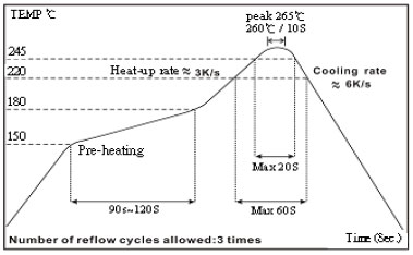
| Resistance to Soldering Heat | Appearance: No damage | Pre-heating: 150°C, 1min. Solder Temperature: 260 ± 5°C Immersion Time: 10 ± 1 seconds |
| Vibration | Appearance: No damage L change: within ± 10% Q change: within ± 30% DCR: within specification | Test device shall be soldered on the substrate Oscillation Frequency: 10 to 55 to 10Hz for 1 min. Amplitude: 1.5 mm Time: 2 hrs for each axis (X, Y & Z), total 6 hrs |
Climatic Test
| Item | Requirement | Test Method | |||||||||||||||
|---|---|---|---|---|---|---|---|---|---|---|---|---|---|---|---|---|---|
| Temperature Cycle | Appearance: No damage L change: within ± 10% Q change: within ± 30% DCR: within specification | One cycle:
Total: 100 cycles | |||||||||||||||
| Damp Heat with Load | Temperature: 40 ± 2°C Relative Humidity: 90 ~ 95% Time: 1000 hrs Measured after exposure in the room condition for 24 hrs | ||||||||||||||||
| High Temperature Storage | Temperature: 85 ± 3°C Applied Current: Rated Current Time: 1000 hrs Measured after exposure in the room condition for 24 hrs | ||||||||||||||||
| Low Temperature Storage | Temperature: -25 ± 3°C Time: 1000 hrs Measured after exposure in the room condition for 24 hrs |
☑ Storage Temperature: 15 ~ 28°C; Humidity < 80%RH
☑ Operating Temperature Range: -40 ~ +85°C
Packaging Quantity & Reel Specifications (Unit : mm)
| Type | Ø A | Ø B | Ø C | W | T | Quantity (EA) | 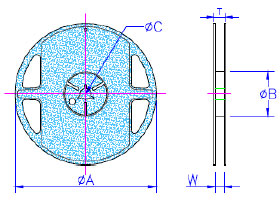 |
|---|---|---|---|---|---|---|---|
| NL03 | 178 ± 2.0 | 60 ± 0.5 | 13 ± 0.3 | 9 ± 0.3 | 12 ± 1.0 | 4000 | |
| NL05 | 178 ± 2.0 | 60 ± 0.5 | 13 ± 0.3 | 9 ± 0.3 | 12 ± 1.0 | 2000 | |
| NL08 | 178 ± 2.0 | 60 ± 0.5 | 13 ± 0.3 | 9 ± 0.3 | 12 ± 1.0 | 2000 | |
| NL10 | 178 ± 2.0 | 60 ± 0.5 | 13 ± 0.3 | 9 ± 0.3 | 12 ± 1.0 | 2000 | |
| NL12 | 178 ± 2.0 | 80 ± 0.5 | 13 ± 0.3 | 13.2 ± 0.3 | 16 ± 1.0 | 500 | |
| NL20 | 330 ± 2.0 | 100 ± 0.5 | 13 ± 0.3 | 17.4 ± 0.3 | 22 ± 1.0 | 1000 |
Embossed Plastic Tape Specifications (Unit : mm)
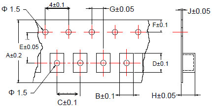
| Type | A | B | C | D | E | F | G | H | J |
|---|---|---|---|---|---|---|---|---|---|
| NL03 | 8 | 1.25 | 4 | 1.90 | 3.5 | 1.75 | 2 | 1.00 | 0.23 |
| NL05 | 8 | 1.85 | 4 | 2.55 | 3.5 | 1.75 | 2 | 1.45 | 0.23 |
| NL08 | 8 | 2.80 | 4 | 2.95 | 3.5 | 1.75 | 2 | 2.22 | 0.23 |
| NL10 | 8 | 2.96 | 4 | 3.60 | 3.5 | 1.75 | 2 | 2.40 | 0.23 |
| NL12 | 12 | 3.30 | 8 | 5.00 | 5.5 | 1.75 | 2 | 3.50 | 0.30 |
| NL20 | 16 | 5.35 | 12 | 6.10 | 7.5 | 1.75 | 2 | 5.50 | 0.35 |
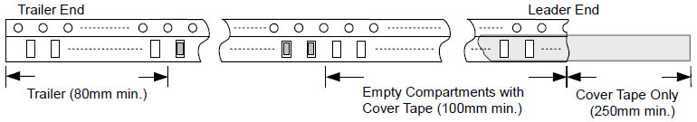
Leader / Trailer Tape
Cover Tape Peel Strength
The force for tearing off cover tape is 0.1 ~ 0.6 (N) in the arrow direction at the following conditions: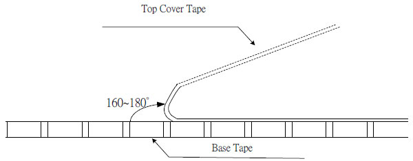

Résistance de précision en film mince 0,01 %, TC2ppm, wirebondale, anti-corrosion, MELF. Détection...
Lire la suite
Inducteurs céramiques haute fréquence, de petite taille jusqu'à 01005. Film mince, multicouche, bobiné,...
Lire la suite
Le condensateur céramique multicouche offre une haute tension, une haute fréquence, un faible bruit,...
Lire la suite