




AUTOMOBILANWENDUNGEN
Dünnschicht-Präzisionswiderstand 0,01%, TC2ppm, Drahtbondable, Antikorrosiv, MELF. Stromsensoren, Metall,...
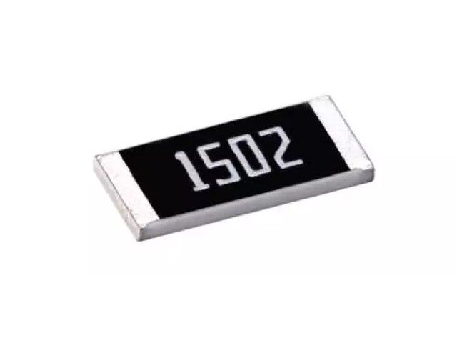
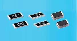
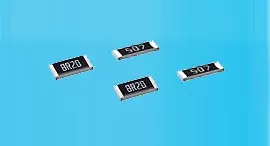
WeiterlesenSurge-/Pulschutz ist für alle Schaltungsdesigns unerlässlich. SWR-Serie, Größen von 0402-2512, Toleranz 5%~10%, 1 Ohm~20 MOhm. Mehr Schaltungsdesign wird immer wichtiger. Surge-/Pulschutz ist für alle Schaltungsdesigns unerlässlich. Die SWR-Serie von Viking, unbeschnitten auf der Widerstandsschicht, bleibt der überlegene Puls- und ESD-beständige Widerstand, der zum Schutz elektronischer Schaltungen gegen extreme Pulse und Überspannungen geeignet ist. Widerstände, die den Puls oder die Überspannung standhalten, sind in Schaltungen erforderlich, in denen große Ströme sofort angewendet oder ESD angewendet wird. Surge bedeutet Überlastung wie ESD oder Hochspannung mit kurzer Dauer. Anti-Überstromwiderstände können Schäden durch große, sofort angelegte Leistungen verhindern.Viking - IATF16949/ISO-9001/ISO-14001 zertifizierte Dünn-/Dickschichtprozesse und OEM-Dienstleistungen für die Automobil- und Elektronikgeräteanwendungen. Beschichtung, Lithographie, maßgeschneiderte Gestaltung bei Dünn-/Dickenfilmprozessen. 100% CCD-Inspektion. Kleine Größe & leichtes Gewicht. Geeignet für IR-Umschmelzlöten. Mit mehr als 20 Jahren Erfahrung ist Viking auf die Herstellung von Dünnschicht-Chipwiderständen, Chipwiderständen, Leistungsinduktivitäten, Strommesswiderständen, Dickschichtwiderständen, Chipkondensatoren und keramischen Substraten spezialisiert.

Surge-/Pulschutz ist für alle Schaltungsdesigns unerlässlich. SWR-Serie, Größen von 0402-2512, Toleranz 5%~10%, 1 Ohm~20 MOhm. Mehr Schaltungsdesign wird immer wichtiger. Surge-/Pulschutz ist für alle Schaltungsdesigns unerlässlich. Die SWR-Serie von Viking, unbeschnitten auf der Widerstandsschicht, bleibt der überlegene Puls- und ESD-beständige Widerstand, der zum Schutz elektronischer Schaltungen gegen extreme Pulse und Überspannungen geeignet ist. Widerstände, die den Puls oder die Überspannung standhalten, sind in Schaltungen erforderlich, in denen große Ströme sofort angewendet oder ESD angewendet wird. Surge bedeutet Überlastung wie ESD oder Hochspannung mit kurzer Dauer. Anti-Überstromwiderstände können Schäden durch große, sofort angelegte Leistungen verhindern.
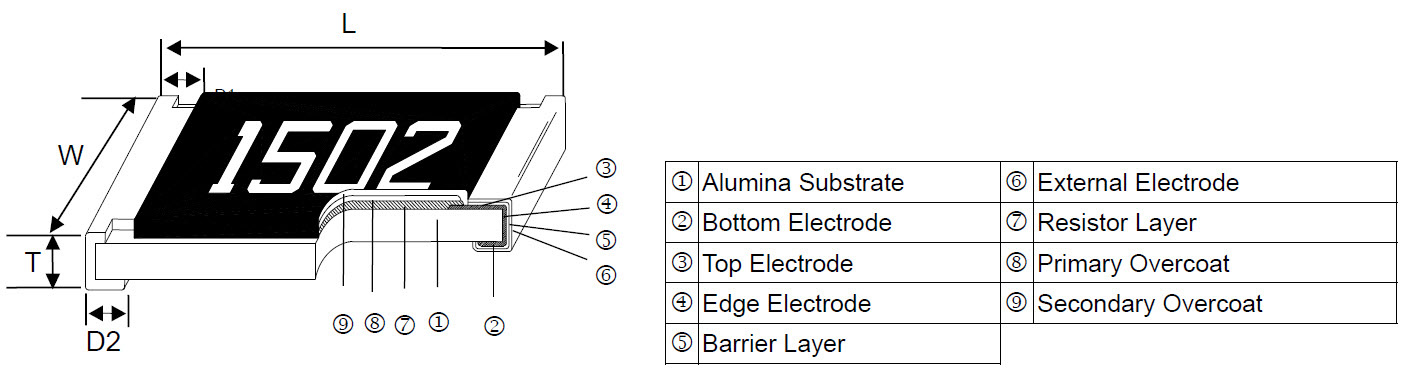
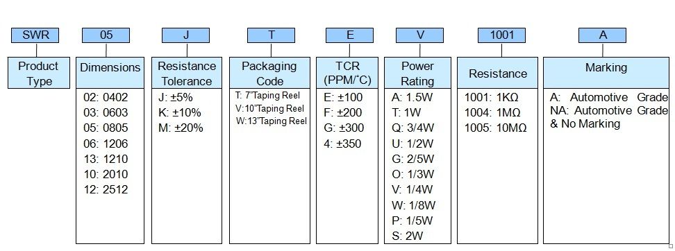
| Item Type |
Power Rating at 70°C |
Operating Temp. Range |
Max. Operating Voltage |
Max. Overload Voltage |
Resistance Range | TCR (PPM/°C) |
||
|---|---|---|---|---|---|---|---|---|
| ±5% (E24) | ±10% (E24) | ±20% (E24) | ||||||
| SWR02 (0402) | 1/5W | -55 ~ +155°C | 50V | 100V | 1Ω - 20Ω | ±300 | ||
| 22Ω - 1MΩ | ±100 | |||||||
| SWR03 (0603) | 1/8W | -55 ~ +155°C | 50V | 100V | 1Ω - 270Ω | ±200 | ||
| 300Ω - 1MΩ | ±100 | |||||||
| SWR05 (0805) | 1/4W | -55 ~ +155°C | 150V | 300V | 1Ω - 270Ω | ±200 | ||
| 300Ω - 20MΩ | ±100 | |||||||
| SWR06 (1206) | 1/3W | -55 ~ +155°C | 200V | 400V | 1Ω - 20Ω | ±200 | ||
| 22Ω - 20MΩ | ±100 | |||||||
| SWR13 (1210) | 1/2W | -55 ~ +155°C | 200V | 400V | 1Ω - 20Ω | ±200 | ||
| 22Ω - 20MΩ | ±100 | |||||||
| SWR10 (2010) | 3/4W | -55 ~ +155°C | 400V | 800V | 1Ω - 20Ω | ±200 | ||
| 22Ω - 20MΩ | ±100 | |||||||
| SWR12 (2512) | 1.5W | -55 ~ +155°C | 500V | 1000V | 1Ω - 20Ω | ±200 | ||
| 22Ω - 20MΩ | ±100 | |||||||
Operating Voltage=√(P*R) or Max. Operating Voltage listed above, whichever is lower.
Overload Voltage=2.5*√(P*R) or Max. Overload Voltage listed above, whichever is lower.
☑ Viking is capable of manufacturing the optional spec based on customer's requirement.
The single impulse graph is the result of 50 impulses of rectangular shape applied at one-minute intervals. The limit of acceptance was a shift in resistance of less than 1% from the initial value. The power applied was subject to the restrictions of the maximum permissible impulse voltage graph shown.
The continuous load graph was obtained by applying repetitive rectangular pulses where the pulse period was adjusted so that the average power dissipated in the resistor was equal to its rated power at 70°C. Again the limit of acceptance was a shift in resistance of less than 1% from the initial value.
Resistors are tested in accordance with IEC 60115-1 using both 1.2/50us and 10/700 pulse shapes. The limit of acceptance is a shift in resistance of less than 1% from the initial value.
Dünnschicht-Präzisionswiderstand 0,01%, TC2ppm, Drahtbondable, Antikorrosiv, MELF. Stromsensoren, Metall,...
Weiterlesen
Keramische Hochfrequenz-Chip-Induktoren, klein bis 01005. Dünnschicht-, Mehrschicht-, Drahtgewickelte-,...
Weiterlesen
Multilayer-Keramikkondensatoren bieten hohe Spannung, hohe Frequenz, niedrigen Geräuschpegel, hohe Q, niedrigen...
Weiterlesen