


APPLICATIONS AUTOMOBILES
Résistance de précision en film mince 0,01 %, TC2ppm, wirebondale, anti-corrosion, MELF. Détection...
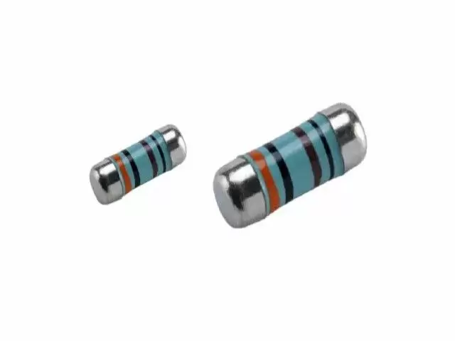
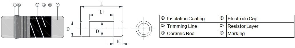
Lire la suiteLe MELF est de forme cylindrique et avec une résistance à face métallique sans plomb. Les tailles de motif de montage sont les mêmes que celles des résistances SMD. Il est fabriqué en déposant un film homogène de NiCr sur un corps céramique de haute qualité. La haute qualité des résistances MELF offre une excellente stabilité électrique et environnementale, une stabilité exceptionnelle démontrée au cours de la vie, en humidité biaisée et lors des tests de surcharge à court terme. Délai de livraison court, contrôle des coûts efficace, compétitivité des prixViking - Processus de film mince/épais certifié IATF16949/ISO-9001/ISO-14001 et services OEM pour les applications automobiles et dispositifs électroniques. Revêtement, lithographie, conception sur mesure pour les processus de films fins/épais. Inspection CCD à 100 %. Petite taille et léger. Convient au soudage par refusion IR. Avec plus de 20 ans d'expérience, Viking est spécialisé dans la fabrication de résistances à film mince, résistances de puce, inducteurs de puissance, résistances de détection de courant, résistances à film épais, condensateurs de puce et substrats en céramique.

Le MELF est de forme cylindrique et avec une résistance à face métallique sans plomb. Les tailles de motif de montage sont les mêmes que celles des résistances SMD.
Il est fabriqué en déposant un film homogène de NiCr sur un corps céramique de haute qualité. La haute qualité des résistances MELF offre une excellente stabilité électrique et environnementale, une stabilité exceptionnelle démontrée au cours de la vie, en humidité biaisée et lors des tests de surcharge à court terme.
Délai de livraison court, contrôle des coûts efficace, compétitivité des prix
| DESCRIPTION | CSRV0102 | CSRV0204 | CSRV0207 | ||||
|---|---|---|---|---|---|---|---|
| Resistance range | 0.22Ω - 1MΩ; 0Ω | 0.1Ω - 10MΩ; 0Ω | 0.1Ω - 10MΩ; 0Ω | ||||
| Resistance tolerance | ± 5%;± 1%;± 0.5%;± 0.25%;± 0.1% | ||||||
| Temperature coefficient | ± 100ppm/°C; ± 50ppm/°C; ± 25ppm/°C; ± 15ppm/°C |
± 100ppm/°C; ± 50ppm/°C; ± 25ppm/°C; ± 15ppm/°C; ± 10ppm/°C |
|||||
| Operation mode | Standard | High power | Standard | High power | Standard | High power | |
| Power rating P70 | 1/8W | 1/5W | 0.3W | 1/4W | 2/5W | 1/2W | 1W |
| Operating voltage Umax. | 150V | 200V | 200V | 200V | 200V | 300V | 350V |
| Operating temperature range | -55°C ~ 155°C | ||||||
| Max. resistance change at P70 for resistance range, ΔR/R max., after 1000 h | ≦ 0.5% | ≦ 0.5% | ≦ 0.5% | ||||
| Item Type |
Power Rating at 70°C | Operating Temp. Range | Max. Operating Voltage | Max. Overload Voltage | Resistance Range | TCR (PPM/°C) | |||||||
|---|---|---|---|---|---|---|---|---|---|---|---|---|---|
| ± 0.1% (E24,E96) | ± 0.25% (E24,E96) | ± 0.5% (E24,E96) | ± 1% (E24,E96) | ± 5% (E24) | |||||||||
| 0102 | 1/8W | -55 ~ +155°C | 150V | 300V | 49.9Ω - 56KΩ | - | ± 15 | ||||||
| 100Ω - 82KΩ | 4.02Ω- 200KΩ | 4.02Ω- 390KΩ | - | ± 25 | |||||||||
| - | 1Ω - 1MΩ | 0.22Ω - 1MΩ | ± 50 | ||||||||||
| - | 0.22Ω - 1MΩ | ± 100 | |||||||||||
| 0204 | 1/4W | -55 ~ +155°C | 200V | 400V | 10Ω - 332KΩ | - | ± 5 | ||||||
| 10Ω - 20KΩ | - | ± 10 | |||||||||||
| 10Ω - 300KΩ | - | ± 15 | |||||||||||
| 10Ω - 1MΩ | 10Ω - 3.4MΩ | 1Ω - 3.4MΩ | ± 25 | ||||||||||
| 10Ω - 1MΩ | 1Ω - 3.4MΩ | 0.2Ω - 10MΩ | ± 50 | ||||||||||
| - | 0.1Ω-10MΩ | ± 100 | |||||||||||
| 0207 | 1/2W | -55 ~ +155°C | 300V | 600V | 10Ω - 332KΩ | - | ± 5 | ||||||
| 10Ω - 20KΩ | - | ± 10 | |||||||||||
| 10Ω - 300KΩ | - | ± 15 | |||||||||||
| 10Ω - 1MΩ | 10Ω - 3.4MΩ | 1Ω - 3.4MΩ | ± 25 | ||||||||||
| 10Ω - 1MΩ | 1Ω - 3.4MΩ | 0.2Ω - 10MΩ | ± 50 | ||||||||||
| - | 0.1Ω - 10MΩ | ± 100 | |||||||||||
The single impulse graph is the result of the impulse of rectangular shape applied. The limit of acceptance was a shift in resistance of less than 1% from the initial value. The power applied was subject to the restrictions of the maximum permissible impulse voltage graph shown.
The continuous load graph was obtained by applying repetitive rectangular pulses where the pulse period was adjusted so that the average power dissipated in the resistor was equal to its rated power at 70℃. Again the limit of acceptance was a shift in resistance of less than 1% from the initial value.
Resistors are designed to function according to ohmic laws. This is basically true of resistors for frequencies up to 100kHz. At higher frequencies, there is an additional contribution to the impedance by an ideal resistor switched in series with a coil and both switched parallel to a capacitor. The values of the capacitance and inductance are mainly determined by the dimensions of the terminations and the conductive path length.
The environment surrounding components has a large influence on the behavior of the component on the printed-circuit board.
Resistors are tested in accordance with IEC 60115-1 using both 1.2/50us and 10/700us pulse shapes. The limit of acceptance is a shift in resistance of less than 0.5% from the initial value.

Résistance de précision en film mince 0,01 %, TC2ppm, wirebondale, anti-corrosion, MELF. Détection...
Lire la suite
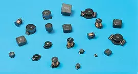
Inducteurs céramiques haute fréquence, de petite taille jusqu'à 01005. Film mince, multicouche, bobiné,...
Lire la suite
Le condensateur céramique multicouche offre une haute tension, une haute fréquence, un faible bruit,...
Lire la suite