

自動車アプリケーション
薄膜精密抵抗器0.01%、TC2ppm、ワイヤーボンダブル、防錆性、MELF。 電流センシング、金属、耐硫黄、サージ、高電圧、TO220/247パッケージ最大100Wまで
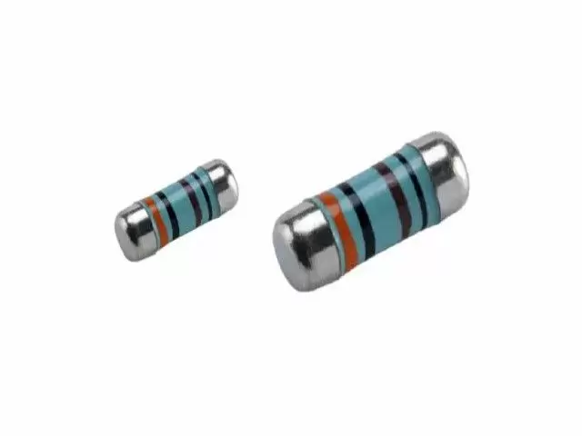
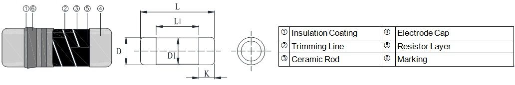
続きを読むMELFは円筒形で、金属電極のリードレス面実装抵抗器です。ランドパターンサイズはSMDチップ抵抗器と同じです。 これは、高品質のセラミックボディに均一なNiCrフィルムを堆積させて製造されます。MELF抵抗器の高品質は、優れた電気的および環境的安定性、寿命にわたる優れた安定性、バイアス湿度、短時間過負荷試験で示される卓越した安定性を提供します。 短納期、効果的なコスト管理、価格競争力Viking - IATF16949/ISO-9001/ISO-14001認証の薄膜/厚膜プロセスおよび自動車、電子機器アプリケーション向けのOEMサービス。 コーティング、リソグラフィー、薄膜/厚膜プロセスのカスタムデザイン。 100% CCD検査。 小型で軽量です。 IRリフローはんだ付けに適しています。 20年以上の経験を持つVikingは、薄膜チップ抵抗器、チップ抵抗器、パワーインダクタ、電流センス抵抗器、厚膜抵抗器、チップコンデンサ、セラミック基板の製造を専門としています。

MELFは円筒形で、金属電極のリードレス面実装抵抗器です。ランドパターンサイズはSMDチップ抵抗器と同じです。
これは、高品質のセラミックボディに均一なNiCrフィルムを堆積させて製造されます。MELF抵抗器の高品質は、優れた電気的および環境的安定性、寿命にわたる優れた安定性、バイアス湿度、短時間過負荷試験で示される卓越した安定性を提供します。
短納期、効果的なコスト管理、価格競争力
| DESCRIPTION | CSRV0102 | CSRV0204 | CSRV0207 | ||||
|---|---|---|---|---|---|---|---|
| Resistance range | 0.22Ω - 1MΩ; 0Ω | 0.1Ω - 10MΩ; 0Ω | 0.1Ω - 10MΩ; 0Ω | ||||
| Resistance tolerance | ± 5%;± 1%;± 0.5%;± 0.25%;± 0.1% | ||||||
| Temperature coefficient | ± 100ppm/°C; ± 50ppm/°C; ± 25ppm/°C; ± 15ppm/°C |
± 100ppm/°C; ± 50ppm/°C; ± 25ppm/°C; ± 15ppm/°C; ± 10ppm/°C |
|||||
| Operation mode | Standard | High power | Standard | High power | Standard | High power | |
| Power rating P70 | 1/8W | 1/5W | 0.3W | 1/4W | 2/5W | 1/2W | 1W |
| Operating voltage Umax. | 150V | 200V | 200V | 200V | 200V | 300V | 350V |
| Operating temperature range | -55°C ~ 155°C | ||||||
| Max. resistance change at P70 for resistance range, ΔR/R max., after 1000 h | ≦ 0.5% | ≦ 0.5% | ≦ 0.5% | ||||
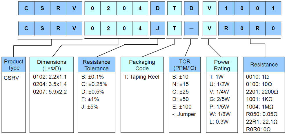
| Item Type |
Power Rating at 70°C | Operating Temp. Range | Max. Operating Voltage | Max. Overload Voltage | Resistance Range | TCR (PPM/°C) | |||||||
|---|---|---|---|---|---|---|---|---|---|---|---|---|---|
| ± 0.1% (E24,E96) | ± 0.25% (E24,E96) | ± 0.5% (E24,E96) | ± 1% (E24,E96) | ± 5% (E24) | |||||||||
| 0102 | 1/8W | -55 ~ +155°C | 150V | 300V | 49.9Ω - 56KΩ | - | ± 15 | ||||||
| 100Ω - 82KΩ | 4.02Ω- 200KΩ | 4.02Ω- 390KΩ | - | ± 25 | |||||||||
| - | 1Ω - 1MΩ | 0.22Ω - 1MΩ | ± 50 | ||||||||||
| - | 0.22Ω - 1MΩ | ± 100 | |||||||||||
| 0204 | 1/4W | -55 ~ +155°C | 200V | 400V | 10Ω - 332KΩ | - | ± 5 | ||||||
| 10Ω - 20KΩ | - | ± 10 | |||||||||||
| 10Ω - 300KΩ | - | ± 15 | |||||||||||
| 10Ω - 1MΩ | 10Ω - 3.4MΩ | 1Ω - 3.4MΩ | ± 25 | ||||||||||
| 10Ω - 1MΩ | 1Ω - 3.4MΩ | 0.2Ω - 10MΩ | ± 50 | ||||||||||
| - | 0.1Ω-10MΩ | ± 100 | |||||||||||
| 0207 | 1/2W | -55 ~ +155°C | 300V | 600V | 10Ω - 332KΩ | - | ± 5 | ||||||
| 10Ω - 20KΩ | - | ± 10 | |||||||||||
| 10Ω - 300KΩ | - | ± 15 | |||||||||||
| 10Ω - 1MΩ | 10Ω - 3.4MΩ | 1Ω - 3.4MΩ | ± 25 | ||||||||||
| 10Ω - 1MΩ | 1Ω - 3.4MΩ | 0.2Ω - 10MΩ | ± 50 | ||||||||||
| - | 0.1Ω - 10MΩ | ± 100 | |||||||||||
The single impulse graph is the result of the impulse of rectangular shape applied. The limit of acceptance was a shift in resistance of less than 1% from the initial value. The power applied was subject to the restrictions of the maximum permissible impulse voltage graph shown.
The continuous load graph was obtained by applying repetitive rectangular pulses where the pulse period was adjusted so that the average power dissipated in the resistor was equal to its rated power at 70℃. Again the limit of acceptance was a shift in resistance of less than 1% from the initial value.
Resistors are designed to function according to ohmic laws. This is basically true of resistors for frequencies up to 100kHz. At higher frequencies, there is an additional contribution to the impedance by an ideal resistor switched in series with a coil and both switched parallel to a capacitor. The values of the capacitance and inductance are mainly determined by the dimensions of the terminations and the conductive path length.
The environment surrounding components has a large influence on the behavior of the component on the printed-circuit board.
Resistors are tested in accordance with IEC 60115-1 using both 1.2/50us and 10/700us pulse shapes. The limit of acceptance is a shift in resistance of less than 0.5% from the initial value.

薄膜精密抵抗器0.01%、TC2ppm、ワイヤーボンダブル、防錆性、MELF。 電流センシング、金属、耐硫黄、サージ、高電圧、TO220/247パッケージ最大100Wまで
続きを読む