
APPLICAZIONI AUTOMOTIVE
Resistore di precisione a film sottile 0,01%, TC2ppm, wirebondale, anti-corrosivo, MELF. Rilevamento...
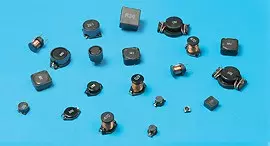
Leggi di piùCon sede a Taiwan, Viking Tech Corporation è uno dei principali produttori di Induttore a chip avvolto in filo (Ferrite) (Serie NL NL05JTR62) dal 1997.TS16949/ ISO9001/ ISO1400, soddisfano gli standard AEC-Q200 e i prodotti sono utilizzati per applicazioni automobilistiche e dispositivi elettronici.Viking fornisce resistori di precisione anti-zolfo, anti-sbalzo, a impulsi, ad alta tensione e ad alta potenza, inclusi resistori a film sottile/spesso, resistori automobilistici, resistori melf e resistori di rilevamento della corrente.Induttori a bassa rumorosità, bassa TC e alta potenza come induttori RF, induttori a chip, induttori di potenza, induttori variabili, induttori a chip in ferrite, induttori schermati, induttori avvolti in filo e induttori a immersione.Viking ha offerto ai clienti resistori di potenza, induttori di potenza e condensatori elettrolitici in alluminio di alta qualità con una solida reputazione.Con oltre 20 anni di esperienza, Viking è specializzata nella produzione di resistori a film sottile, resistori a chip, induttori di potenza, resistori di rilevamento corrente, resistori a film spesso, condensatori a chip e substrati ceramici.
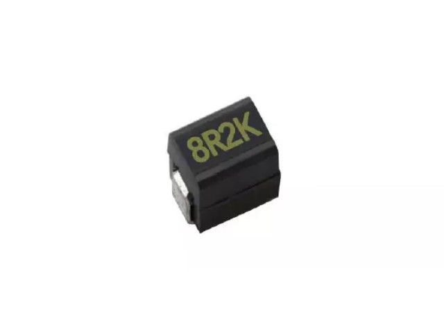
Induttore in ferrite a chip avvolto in filo, disponibile in alta corrente, tipo stampato e aperto. Dimensioni ridotte fino a 0603, ottima saldabilità tramite saldatura a flusso o saldatore, saldatura a onda. Altamente resistente agli urti meccanici e alla pressione. Estremamente affidabile in ambienti con cambiamenti di temperatura improvvisi e umidità. Caratteristiche super Q.
NL Series0805 ±5% 0.62μH 0.5 Ω 980mA 30 640
| Dimensione | Tolleranza | Induttanza | Condizione di test | DCR (Ω) max. | IDC (mA) | Q | SRF |
|---|---|---|---|---|---|---|---|
| 0805 | ±5% | 0.62 | 25MHz | 0.5 | 980 | 30 | 640 |
NL03 Wound Chip Inductors (Ferrite / Open Type) / Large Current Type
| Codes | Inductance (uH) | Tolerance | Q min. | Test Freq. (MHz) | SRF (MHz) min. | DCR (Ω) max. | IDC (mA) max. | Color Code |
|---|---|---|---|---|---|---|---|---|
| R10 | 0.10 | ± 5, ± 10, ± 20% | 12 | 7.9 | 1150 | 0.13 | 1700 | Black |
| R12 | 0.12 | ± 5, ± 10, ± 20% | 12 | 7.9 | 1100 | 0.15 | 1700 | Orange |
| R15 | 0.15 | ± 5, ± 10, ± 20% | 15 | 7.9 | 1050 | 0.15 | 1600 | Brown |
| R18 | 0.18 | ± 5, ± 10, ± 20% | 15 | 7.9 | 950 | 0.15 | 1500 | Green |
| R22 | 0.22 | ± 5, ± 10, ± 20% | 15 | 7.9 | 900 | 0.30 | 1200 | Red |
| R24 | 0.24 | ± 5, ± 10, ± 20% | 15 | 7.9 | 850 | 0.16 | 1460 | Green |
| R27 | 0.27 | ± 5, ± 10, ± 20% | 15 | 7.9 | 835 | 0.30 | 1460 | Yellow |
| R33 | 0.33 | ± 5, ± 10, ± 20% | 15 | 7.9 | 725 | 0.40 | 1420 | Orange |
| R39 | 0.39 | ± 5, ± 10, ± 20% | 15 | 7.9 | 680 | 0.41 | 1400 | Blue |
| R47 | 0.47 | ± 5, ± 10, ± 20% | 15 | 7.9 | 640 | 0.43 | 1400 | Black |
| R56 | 0.56 | ± 5, ± 10, ± 20% | 15 | 7.9 | 630 | 0.44 | 1400 | Brown |
| R68 | 0.68 | ± 5, ± 10, ± 20% | 15 | 7.9 | 510 | 0.52 | 1340 | Red |
| R78 | 0.78 | ± 5, ± 10, ± 20% | 15 | 7.9 | 465 | 0.63 | 1300 | Orange |
| R82 | 0.82 | ± 5, ± 10, ± 20% | 15 | 7.9 | 460 | 0.69 | 1200 | Yellow |
| 1R0 | 1.0 | ± 5, ± 10, ± 20% | 15 | 7.9 | 320 | 0.81 | 1100 | Green |
| 1R2 | 1.2 | ± 5, ± 10, ± 20% | 15 | 7.9 | 270 | 0.87 | 1100 | Blue |
| 1R5 | 1.5 | ± 5, ± 10, ± 20% | 15 | 7.9 | 230 | 0.96 | 920 | Violet |
| 1R8 | 1.8 | ± 5, ± 10, ± 20% | 15 | 7.9 | 210 | 1.10 | 900 | Gray |
| 2R2 | 2.2 | ± 5, ± 10, ± 20% | 15 | 7.9 | 115 | 1.20 | 740 | White |
| 2R7 | 2.7 | ± 5, ± 10, ± 20% | 15 | 7.9 | 100 | 1.38 | 700 | Black |
| 3R3 | 3.3 | ± 5, ± 10, ± 20% | 15 | 7.9 | 84 | 1.50 | 680 | Brown |
| 3R9 | 3.9 | ± 5, ± 10, ± 20% | 15 | 7.9 | 75 | 1.50 | 600 | Red |
| 4R7 | 4.7 | ± 5, ± 10, ± 20% | 15 | 7.9 | 67 | 2.10 | 580 | Orange |
| 5R6 | 5.6 | ± 5, ± 10, ± 20% | 15 | 7.9 | 55 | 2.37 | 540 | Yellow |
| 6R8 | 6.8 | ± 5, ± 10, ± 20% | 15 | 7.9 | 48 | 3.10 | 500 | Green |
| 7R8 | 7.8 | ± 5, ± 10, ± 20% | 15 | 7.9 | 40 | 3.35 | 460 | Blue |
| 8R2 | 8.2 | ± 5, ± 10, ± 20% | 15 | 7.9 | 38 | 3.50 | 440 | Violet |
| 100 | 10 | ± 5, ± 10, ± 20% | 15 | 7.9 | 32 | 4.46 | 400 | Gray |
NL05 Wire Wound Chip Inductors (Ferrite / Open Type) / Large Current Type
| Codes | Inductance (uH) | Tolerance | Q typ. | Test Freq. (MHz) | SRF (MHz) typ. | DCR (Ω) max. | IDC (mA) typ. | Color Code |
|---|---|---|---|---|---|---|---|---|
| R47 | 0.47 | ± 5, ± 10, ± 20% | 14 | 7.9 | 850 | 0.156 | 1400 | Blue |
| R68 | 0.68 | ± 5, ± 10, ± 20% | 14 | 7.9 | 765 | 0.195 | 1200 | Gray |
| 1R0 | 1.00 | ± 5, ± 10, ± 20% | 14 | 7.9 | 208 | 0.169 | 1100 | Black |
| 1R2 | 1.20 | ± 5, ± 10, ± 20% | 14 | 7.9 | 159 | 0.208 | 960 | Red |
| 1R5 | 1.50 | ± 5, ± 10, ± 20% | 14 | 7.9 | 159 | 0.221 | 920 | Brown |
| 1R8 | 1.80 | ± 5, ± 10, ± 20% | 14 | 7.9 | 112 | 0.260 | 860 | Orange |
| 2R2 | 2.20 | ± 5, ± 10, ± 20% | 13 | 7.9 | 87 | 0.286 | 740 | Red |
| 2R7 | 2.70 | ± 5, ± 10, ± 20% | 13 | 7.9 | 72 | 0.325 | 680 | Yellow |
| 3R3 | 3.30 | ± 5, ± 10, ± 20% | 12 | 7.9 | 70 | 0.364 | 620 | Orange |
| 3R9 | 3.90 | ± 5, ± 10, ± 20% | 14 | 7.9 | 61 | 0.494 | 580 | Green |
| 4R7 | 4.70 | ± 5, ± 10, ± 20% | 14 | 7.9 | 51 | 0.559 | 520 | Yellow |
| 5R6 | 5.60 | ± 5, ± 10, ± 20% | 12 | 7.9 | 47 | 0.650 | 480 | Blue |
| 6R8 | 6.80 | ± 5, ± 10, ± 20% | 14 | 7.9 | 46 | 0.884 | 420 | Green |
| 8R2 | 8.20 | ± 5, ± 10, ± 20% | 13 | 7.9 | 33 | 0.949 | 400 | Violet |
| 100 | 10 | ± 5, ± 10, ± 20% | 14 | 2.5 | 31 | 1.105 | 360 | Blue |
| 120 | 12 | ± 5, ± 10, ± 20% | 14 | 2.5 | 30 | 1.17 | 340 | Gray |
| 150 | 15 | ± 5, ± 10, ± 20% | 15 | 2.5 | 28 | 1.82 | 300 | Violet |
| 180 | 18 | ± 5, ± 10, ± 20% | 15 | 2.5 | 27 | 2.01 | 280 | White |
| 220 | 22 | ± 5, ± 10, ± 20% | 15 | 2.5 | 20 | 2.288 | 240 | Gray |
| 270 | 27 | ± 5, ± 10, ± 20% | 15 | 2.5 | 17 | 2.60 | 220 | Black |
| 330 | 33 | ± 5, ± 10, ± 20% | 15 | 2.5 | 17 | 3.055 | 200 | White |
| 470 | 47 | ± 5, ± 10, ± 20% | 14 | 2.5 | 15 | 4.42 | 160 | Black |
| 560 | 56 | ± 5, ± 10, ± 20% | 14 | 2.5 | 10 | 5.746 | 150 | Yellow |
| 680 | 68 | ± 5, ± 10, ± 20% | 14 | 2.5 | 10 | 5.785 | 140 | Brown |
| 820 | 82 | ± 5, ± 10, ± 20% | 14 | 2.5 | 10 | 9.75 | 100 | Orange |
| 101 | 100 | ± 5, ± 10, ± 20% | 10 | 1 | 9 | 9.75 | 100 | Red |
NL10 Wire Wound Chip Inductors (Ferrite / Molding Type) / Large Current Type
| Codes | Inductance (uH) | Tolerance | Q min. | Test Freq. (MHz) | SRF (MHz) typ. | DCR (Ω) max. | IDC (mA) max. |
|---|---|---|---|---|---|---|---|
| 1R0 | 1.0 | ± 5%,± 20% | 10 | 7.96 | 145 | 0.156 | 770 |
| 1R5 | 1.5 | ± 5%,± 20% | 10 | 7.96 | 100 | 0.195 | 580 |
| 2R2 | 2.2 | ± 5%,± 20% | 10 | 7.96 | 80 | 0.260 | 480 |
| 3R3 | 3.3 | ± 5%,± 20% | 10 | 7.96 | 60 | 0.325 | 400 |
| 4R7 | 4.7 | ± 5%,± 20% | 10 | 7.96 | 50 | 0.520 | 320 |
| 6R8 | 6.8 | ± 5%,± 20% | 10 | 7.96 | 40 | 0.650 | 280 |
| 100 | 10 | ± 5%,± 10% | 15 | 2.52 | 30 | 1.105 | 220 |
| 150 | 15 | ± 5%,± 10% | 15 | 2.52 | 27 | 1.690 | 180 |
| 220 | 22 | ± 5%,± 10% | 15 | 2.52 | 22 | 2.600 | 145 |
| 270 | 27 | ± 5%,± 10% | 15 | 2.52 | 19 | 3.000 | 125 |
| 330 | 33 | ± 5%,± 10% | 15 | 2.52 | 17 | 3.640 | 115 |
| 470 | 47 | ± 5%,± 10% | 20 | 2.52 | 15 | 5.460 | 105 |
| 680 | 68 | ± 5%,± 10% | 20 | 2.52 | 11 | 8.450 | 85 |
| 820 | 82 | ± 5%,± 10% | 20 | 2.52 | 10 | 8.710 | 80 |
| 101 | 100 | ± 5%,± 10% | 20 | 0.796 | 9 | 10.140 | 75 |
NL12 Wire Wound Chip Inductors (Ferrite / Molding Type) / Large Current Type
| Codes | Inductance (uH) | Tolerance | Q min. | Test Freq. (MHz) | SRF (MHz) typ. | DCR (Ω) max. | IDC (mA) max. |
|---|---|---|---|---|---|---|---|
| 1R0 | 1.0 | ± 5%,± 10% | 10 | 7.96 | 265 | 0.11 | 1050 |
| 1R2 | 1.2 | ± 5%,± 10% | 10 | 7.96 | 180 | 0.12 | 1000 |
| 1R5 | 1.5 | ± 5%,± 10% | 10 | 7.96 | 170 | 0.15 | 950 |
| 1R8 | 1.8 | ± 5%,± 10% | 10 | 7.96 | 105 | 0.16 | 900 |
| 2R2 | 2.2 | ± 5%,± 10% | 10 | 7.96 | 80 | 0.18 | 850 |
| 2R7 | 2.7 | ± 5%,± 10% | 10 | 7.96 | 60 | 0.20 | 800 |
| 3R3 | 3.3 | ± 5%,± 10% | 10 | 7.96 | 55 | 0.22 | 750 |
| 3R9 | 3.9 | ± 5%,± 10% | 10 | 7.96 | 45 | 0.24 | 700 |
| 4R7 | 4.7 | ± 5%,± 10% | 10 | 7.96 | 43 | 0.27 | 650 |
| 5R6 | 5.6 | ± 5%,± 10% | 10 | 7.96 | 40 | 0.30 | 650 |
| 6R8 | 6.8 | ± 5%,± 10% | 10 | 7.96 | 35 | 0.35 | 600 |
| 8R2 | 8.2 | ± 5%,± 10% | 10 | 7.96 | 30 | 0.40 | 600 |
| 100 | 10 | ± 5%,± 10% | 10 | 2.52 | 27 | 0.50 | 550 |
| 120 | 12 | ± 5%,± 10% | 10 | 2.52 | 25 | 0.60 | 500 |
| 150 | 15 | ± 5%,± 10% | 10 | 2.52 | 20 | 0.70 | 450 |
| 180 | 18 | ± 5%,± 10% | 10 | 2.52 | 19 | 0.80 | 400 |
| 220 | 22 | ± 5%,± 10% | 10 | 2.52 | 18 | 0.90 | 370 |
| 270 | 27 | ± 5%,± 10% | 10 | 2.52 | 16 | 1.20 | 330 |
| 330 | 33 | ± 5%,± 10% | 10 | 2.52 | 15 | 1.40 | 300 |
| 390 | 39 | ± 5%,± 10% | 10 | 2.52 | 13 | 1.60 | 280 |
| 470 | 47 | ± 5%,± 10% | 10 | 2.52 | 12 | 1.90 | 260 |
| 560 | 56 | ± 5%,± 10% | 10 | 2.52 | 10 | 2.20 | 240 |
| 680 | 68 | ± 5%,± 10% | 10 | 2.52 | 9.5 | 2.60 | 220 |
| 820 | 82 | ± 5%,± 10% | 10 | 2.52 | 8.5 | 3.50 | 200 |
| 101 | 100 | ± 5%,± 10% | 20 | 0.796 | 8.0 | 4.00 | 180 |
| 121 | 120 | ± 5%,± 10% | 20 | 0.796 | 7.0 | 4.50 | 160 |
| 151 | 150 | ± 5%,± 10% | 20 | 0.796 | 6.5 | 6.50 | 140 |
| 181 | 180 | ± 5%,± 10% | 20 | 0.796 | 6.0 | 7.50 | 120 |
| 221 | 220 | ± 5%,± 10% | 20 | 0.796 | 5.5 | 9.00 | 120 |
| 271 | 270 | ± 5%,± 10% | 20 | 0.796 | 5.0 | 11.0 | 100 |
| 331 | 330 | ± 5%,± 10% | 20 | 0.796 | 4.5 | 13.0 | 90 |
| 391 | 390 | ± 5%,± 10% | 20 | 0.796 | 4.0 | 14.0 | 85 |
| 471 | 470 | ± 5%,± 10% | 20 | 0.796 | 3.5 | 16.0 | 75 |
| 561 | 560 | ± 5%,± 10% | 20 | 0.796 | 3.0 | 21.0 | 70 |
| 681 | 680 | ± 5%,± 10% | 20 | 0.796 | 2.5 | 24.0 | 65 |
NL20 Wire Wound Chip Inductors (Ferrite / Molding Type) / Large Current Type
| Codes | Inductance (uH) | Tolerance | Q min. | Test Freq. (MHz) | SRF (MHz) min. | DCR (Ω) max. | IDC (mA) max. |
|---|---|---|---|---|---|---|---|
| 1R0 | 1.0 | ± 10,± 20% | 10 | 7.96 | 95 | 0.03 | 1800 |
| 1R2 | 1.2 | ± 10, ± 20% | 10 | 7.96 | 70 | 0.035 | 1700 |
| 1R5 | 1.5 | ± 10, ± 20% | 10 | 7.96 | 55 | 0.04 | 1600 |
| 1R8 | 1.8 | ± 10, ± 20% | 10 | 7.96 | 47 | 0.05 | 1400 |
| 2R2 | 2.2 | ± 10, ± 20% | 10 | 7.96 | 42 | 0.06 | 1300 |
| 2R7 | 2.7 | ± 10, ± 20% | 10 | 7.96 | 37 | 0.07 | 1200 |
| 3R3 | 3.3 | ± 10, ± 20% | 10 | 7.96 | 34 | 0.08 | 1120 |
| 3R9 | 3.9 | ± 10, ± 20% | 10 | 7.96 | 32 | 0.09 | 1050 |
| 4R7 | 4.7 | ± 10, ± 20% | 10 | 7.96 | 29 | 0.11 | 950 |
| 5R6 | 5.6 | ± 10, ± 20% | 10 | 7.96 | 26 | 0.13 | 880 |
| 6R8 | 6.8 | ± 10, ± 20% | 10 | 7.96 | 24 | 0.15 | 810 |
| 8R2 | 8.2 | ± 10, ± 20% | 10 | 7.96 | 22 | 0.18 | 750 |
| 100 | 10 | ± 10, ± 20% | 10 | 2.52 | 19 | 0.21 | 690 |
| 120 | 12 | ± 10, ± 20% | 10 | 2.52 | 17 | 0.25 | 630 |
| 150 | 15 | ± 10, ± 20% | 10 | 2.52 | 16 | 0.30 | 580 |
| 180 | 18 | ± 10, ± 20% | 10 | 2.52 | 14 | 0.36 | 530 |
| 220 | 22 | ± 5, ± 10% | 10 | 2.52 | 13 | 0.43 | 480 |
| 270 | 27 | ± 5, ± 10% | 10 | 2.52 | 11.5 | 0.52 | 440 |
| 330 | 33 | ± 5, ± 10% | 10 | 2.52 | 10.5 | 0.62 | 400 |
| 390 | 39 | ± 5, ± 10% | 10 | 2.52 | 9.5 | 0.72 | 370 |
| 470 | 47 | ± 5, ± 10% | 10 | 2.52 | 8.5 | 0.85 | 340 |
| 560 | 56 | ± 5, ± 10% | 10 | 2.52 | 7.8 | 1.00 | 310 |
| 680 | 68 | ± 5, ± 10% | 10 | 2.52 | 7.0 | 1.2 | 290 |
| 820 | 82 | ± 5, ± 10% | 10 | 2.52 | 6.4 | 1.4 | 270 |
| 101 | 100 | ± 5, ± 10% | 20 | 0.796 | 6.0 | 1.6 | 250 |
| 121 | 120 | ± 5, ± 10% | 20 | 0.796 | 5.4 | 1.9 | 230 |
| 151 | 150 | ± 5, ± 10% | 20 | 0.796 | 4.8 | 2.2 | 210 |
| 181 | 180 | ± 5, ± 10% | 20 | 0.796 | 4.4 | 2.8 | 190 |
| 221 | 220 | ± 5, ± 10% | 20 | 0.796 | 3.9 | 3.4 | 170 |
| 271 | 270 | ± 5, ± 10% | 20 | 0.796 | 3.6 | 4.2 | 155 |
| 331 | 330 | ± 5, ± 10% | 20 | 0.796 | 3.2 | 4.9 | 140 |
| 391 | 390 | ± 5, ± 10% | 20 | 0.796 | 2.9 | 5.8 | 130 |
| 471 | 470 | ± 5, ± 10% | 20 | 0.796 | 2.6 | 7.0 | 120 |
| 561 | 560 | ± 5, ± 10% | 20 | 0.796 | 2.4 | 8.5 | 110 |
| 681 | 680 | ± 5, ± 10% | 20 | 0.796 | 2.2 | 10 | 100 |
| 821 | 820 | ± 5, ± 10% | 20 | 0.796 | 2.0 | 13 | 90 |
| 102 | 1000 | ± 5, ± 10% | 20 | 0.252 | 1.8 | 15 | 85 |
Electrical Performance Test
| Item | Requirement | Test Method |
|---|---|---|
| Inductance | Refer to standard electrical characteristic spec. | HP4291 or HP4284 |
| Q | HP4291 or HP4284 | |
| SRF | HP4291 | |
| DC Resistance DCR | Agilent 34401A | |
| Rated Current IDC | Applied the current to coils, The inductance change should be less than 10% to initial value. |
Mechanical Performance Test
| Item | Requirement | Test Method |
|---|---|---|
| Solderability | The electrodes shall be at least 90% covered with new solder coating | Lead-free inductor: after fluxing (alpha 100 or equiv), inductor shall be dipped in a melted solder bath at 245 ± 5°C, 5 ± 0.5 seconds |
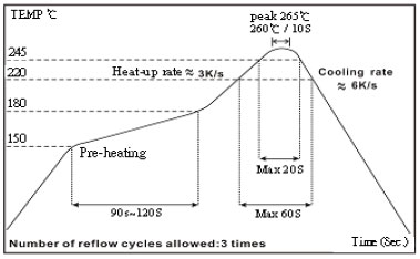
| Resistance to Soldering Heat | Appearance: No damage | Pre-heating: 150°C, 1min. Solder Temperature: 260 ± 5°C Immersion Time: 10 ± 1 seconds |
| Vibration | Appearance: No damage L change: within ± 10% Q change: within ± 30% DCR: within specification |
Test device shall be soldered on the substrate Oscillation Frequency: 10 to 55 to 10Hz for 1 min. Amplitude: 1.5 mm Time: 2 hrs for each axis (X, Y & Z), total 6 hrs |
Climatic Test
| Item | Requirement | Test Method | |||||||||||||||
|---|---|---|---|---|---|---|---|---|---|---|---|---|---|---|---|---|---|
| Temperature Cycle | Appearance: No damage L change: within ± 10% Q change: within ± 30% DCR: within specification |
One cycle:
Total: 100 cycles |
|||||||||||||||
| Damp Heat with Load | Temperature: 40 ± 2°C Relative Humidity: 90 ~ 95% Time: 1000 hrs Measured after exposure in the room condition for 24 hrs |
||||||||||||||||
| High Temperature Storage | Temperature: 85 ± 3°C Applied Current: Rated Current Time: 1000 hrs Measured after exposure in the room condition for 24 hrs |
||||||||||||||||
| Low Temperature Storage | Temperature: -25 ± 3°C Time: 1000 hrs Measured after exposure in the room condition for 24 hrs |
☑ Storage Temperature: 15 ~ 28°C; Humidity < 80%RH
☑ Operating Temperature Range: -40 ~ +85°C
Packaging Quantity & Reel Specifications (Unit : mm)
| Type | Ø A | Ø B | Ø C | W | T | Quantity (EA) | 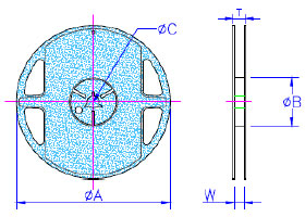 |
|---|---|---|---|---|---|---|---|
| NL03 | 178 ± 2.0 | 60 ± 0.5 | 13 ± 0.3 | 9 ± 0.3 | 12 ± 1.0 | 4000 | |
| NL05 | 178 ± 2.0 | 60 ± 0.5 | 13 ± 0.3 | 9 ± 0.3 | 12 ± 1.0 | 2000 | |
| NL08 | 178 ± 2.0 | 60 ± 0.5 | 13 ± 0.3 | 9 ± 0.3 | 12 ± 1.0 | 2000 | |
| NL10 | 178 ± 2.0 | 60 ± 0.5 | 13 ± 0.3 | 9 ± 0.3 | 12 ± 1.0 | 2000 | |
| NL12 | 178 ± 2.0 | 80 ± 0.5 | 13 ± 0.3 | 13.2 ± 0.3 | 16 ± 1.0 | 500 | |
| NL20 | 330 ± 2.0 | 100 ± 0.5 | 13 ± 0.3 | 17.4 ± 0.3 | 22 ± 1.0 | 1000 |
Embossed Plastic Tape Specifications (Unit : mm)
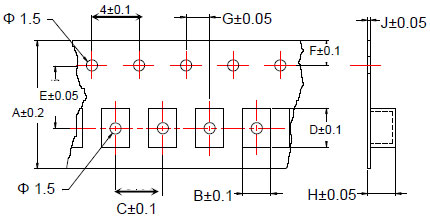
| Type | A | B | C | D | E | F | G | H | J |
|---|---|---|---|---|---|---|---|---|---|
| NL03 | 8 | 1.25 | 4 | 1.90 | 3.5 | 1.75 | 2 | 1.00 | 0.23 |
| NL05 | 8 | 1.85 | 4 | 2.55 | 3.5 | 1.75 | 2 | 1.45 | 0.23 |
| NL08 | 8 | 2.80 | 4 | 2.95 | 3.5 | 1.75 | 2 | 2.22 | 0.23 |
| NL10 | 8 | 2.96 | 4 | 3.60 | 3.5 | 1.75 | 2 | 2.40 | 0.23 |
| NL12 | 12 | 3.30 | 8 | 5.00 | 5.5 | 1.75 | 2 | 3.50 | 0.30 |
| NL20 | 16 | 5.35 | 12 | 6.10 | 7.5 | 1.75 | 2 | 5.50 | 0.35 |
Leader / Trailer Tape
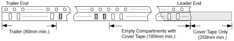
Cover Tape Peel Strength
The force for tearing off cover tape is 0.1 ~ 0.6 (N) in the arrow direction at the following conditions: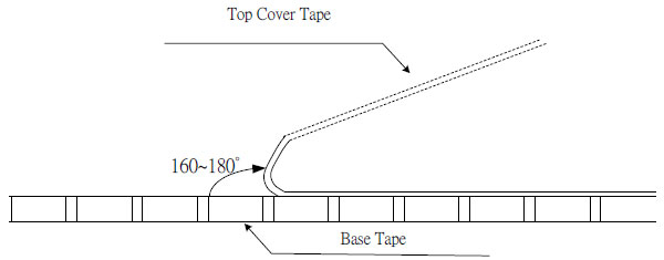

Resistore di precisione a film sottile 0,01%, TC2ppm, wirebondale, anti-corrosivo, MELF. Rilevamento...
Leggi di più
Induttori a chip in ceramica ad alta frequenza, dimensioni ridotte fino a 01005. Induttore a film sottile,...
Leggi di più
Il condensatore ceramico multistrato offre alta tensione, alta frequenza, basso rumore, alta Q, basso...
Leggi di più