


APPLICAZIONI AUTOMOTIVE
Resistore di precisione a film sottile 0,01%, TC2ppm, wirebondale, anti-corrosivo, MELF. Rilevamento...
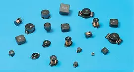
Leggi di piùCon sede a Taiwan, Viking Tech Corporation è uno dei principali produttori di Resistore a chip in striscia metallica a bassa ohm di rilevamento corrente (Serie CSM CSM02FTGVR005) dal 1997.TS16949/ ISO9001/ ISO1400, soddisfano gli standard AEC-Q200 e i prodotti sono utilizzati per applicazioni automobilistiche e dispositivi elettronici.Viking fornisce resistori di precisione anti-zolfo, anti-sbalzo, a impulsi, ad alta tensione e ad alta potenza, inclusi resistori a film sottile/spesso, resistori automobilistici, resistori melf e resistori di rilevamento della corrente.Induttori a bassa rumorosità, bassa TC e alta potenza come induttori RF, induttori a chip, induttori di potenza, induttori variabili, induttori a chip in ferrite, induttori schermati, induttori avvolti in filo e induttori a immersione.Viking ha offerto ai clienti resistori di potenza, induttori di potenza e condensatori elettrolitici in alluminio di alta qualità con una solida reputazione.Con oltre 20 anni di esperienza, Viking è specializzata nella produzione di resistori a film sottile, resistori a chip, induttori di potenza, resistori di rilevamento corrente, resistori a film spesso, condensatori a chip e substrati ceramici.
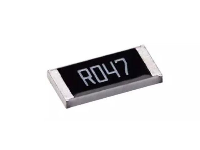
Resistore a striscia metallica a bassa resistenza in corrente - Serie CSM
CSM Series0402 ±1% 300 1/4W Series5Ω 10K/Reel
| Dimensione | Tolleranza | TCR (ppm /℃) | Potenza (W) | Resistenza (Ohm) | Pacchetto |
|---|---|---|---|---|---|
| 0402 | ±1% | 300 | 1/4W | 5 | 10K/Reel |
| Item Type |
Power Rating at 70°C |
Operating Temp. Range | Max. Overload Current |
Resistance Range (mΩ) |
TCR (PPM/°C) |
|||
|---|---|---|---|---|---|---|---|---|
| ±0.5% | ±1% | ±2% | ±5% | |||||
| CSM02 (0402) | 1/4W | -55 ~ +175°C | 15.8A | – | 5 - 6 | ±300 | ||
| 13.4A | – | 7 - 9 | ±200 | |||||
| 11.2A | 30 – 50 | 10 - 50 | ±100 | |||||
| CSM03 (0603) | 1/2W | 22.7A | – | 5 - 6 | ±150 | |||
| 18.9A | – | 7 - 9 | ±100 | |||||
| 15.8A | 30 – 100 | 10 - 100 | ±100 | |||||
| CSM05 (0805) | 3/4W | 27.4A | – | 5 - 9 | ±100 | |||
| 19.4A | 30 – 100 | 10 - 100 | ±50 | |||||
| CSM06 (1206) | 1W | 31.6A | – | 5 - 9 | ±100 | |||
| 22.4A | 30 – 100 | 10 - 100 | ±50 | |||||
| CSM10 (2010) | 1.5W | 38.7A | – | 5 - 9 | ±100 | |||
| 27.4A | 30 – 100 | 10 - 100 | ±50 | |||||
| CSM12 (2512) | 2W | 40.0A | – | 5 - 9 | ±100 | |||
| 28.3A | 30 – 100 | 10 - 100 | ±50 | |||||
Operating Voltage=√(P*R) ; Overload Voltage=2.5*√(P*R) ; Operating Current=√(P/R)
☑ Viking is capable of manufacturing the optional spec based on customer's requirement.
For Standard Power Rating Series
| Item | Requirement | Test Method |
|---|---|---|
| Temperature Coefficient of Resistance (T.C.R.) |
As Spec. | JIS-C-5201-1 4.8 IEC-60115-1 4.8 -55°C~+125°C, 25°C is the reference temperature |
| Short Time Overload | ±(0.5%+0.05Ω) | JIS-C-5201-1 4.13 IEC-60115-1 4.13 5 X Rated Power for 5 seconds |
| Insulation Resistance | ≧10G | JIS-C-5201-1 4.6 IEC-60115-1 4.6 Max. Overload Voltage for 1 minute |
| Endurance | ±(1.0%+0.05Ω) | JIS-C-5201-1 4.25 IEC-60115-1 4.25.1 70±2°C, RCWV for 1000 hrs with 1.5 hrs “ON” and 0.5 hr “OFF” |
| Damp Heat with Load | ±(1.0%+0.05Ω) | JIS-C-5201-1 4.24 IEC-60115-1 4.24 40±2°C, 90~95% R.H., RCWV for 1000 hrs with 1.5 hrs “ON” and 0.5 hr “OFF” |
| Dry Heat | ±(0.5%+0.05Ω) | JIS-C-5201-1 4.23 IEC-60115-1 4.23.2 at +155°C for 1000 hrs |
| Bending Strength | ±(1.0%+0.05Ω) | JIS-C-5201-1 4.33 IEC-60115-1 4.33 Bending once for 60 seconds 2010, 2512 sizes: 2mm Other sizes: 3mm |
| Solderability | 95% min. coverage | JIS-C-5201-1 4.17 IEC-60115-1 4.17 245±5°C for 3 seconds |
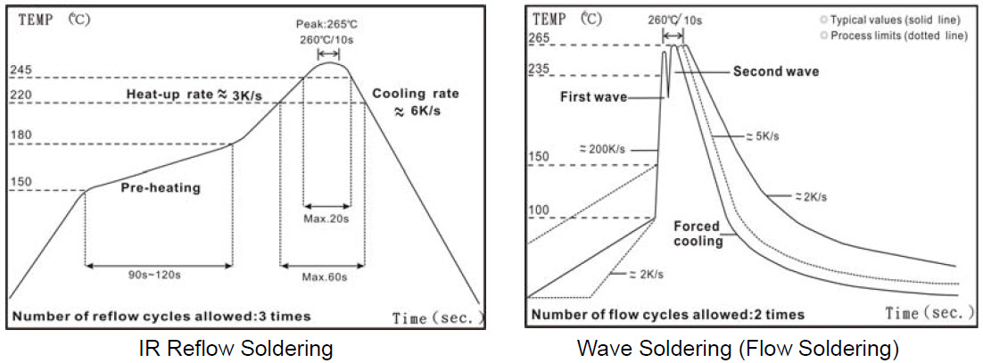
| Resistance to Soldering Heat | ±(0.5%+0.05Ω) | JIS-C-5201-1 4.18 IEC-60115-1 4.18 260±5°C for 10 seconds |
| Voltage Proof | No breakdown or flashover | JIS-C-5201-1 4.7 IEC-60115-1 4.7 1.42 times Max. Operating Voltage for 1 minute |
| Leaching | Individual leaching area ≦5% Total leaching area ≦10% |
JIS-C-5201-1 4.18 IEC-60068-2-58 8.2.1 260±5°C for 30 seconds |
| Rapid Change of Temperature | ±(0.5%+0.05Ω) | JIS-C-5201-1 4.19 IEC-60115-1 4.19 -55°C to +155°C, 5 cycles |
RCWV(Rated Continuous Working Voltage)=√(P*R) or Max. Operating Voltage whichever is lower.
☑ Storage Temperature: 15~28°C; Humidity < 80%RH
For High Power Rating Series
| Item | Requirement | Test Method |
|---|---|---|
| Temperature Coefficient of Resistance (T.C.R.) |
As Spec. | JIS-C-5201-1 4.8 IEC-60115-1 4.8 -55°C~+125°C, 25°C is the reference temperature |
| Short Time Overload | Δ R ≤±1%R | JIS-C-5201-1 4.13 IEC-60115-1 4.13 5 X Rated Power for 5 seconds. 2512 size:4*Rated Power for 5 seconds. Other size:5*Rated Power for 5 seconds. |
| Insulation Resistance | ≧1000MΩ | JIS-C-5201-1 4.6 IEC-60115-1 4.6 Max. Overload Voltage for 1 minute |
| Operational Life | Δ R ≦±1%R | MIL-STD-202 Method 108 Condition D steady state TA=125°C at derated power. Measurement at 24±4 hours after test conclusion |
| Biased Humidity | Δ R ≦±1%R | MIL-STD-202 Method 103 85°C / 85% R.H., 1000 hrs apply 10% of operating power(current) or limiting element current whichever is lower |
| High Temperature Exposure | Δ R ≦±1%R | MIL-STD-202 Method 108 at +155°C for 1000 hrs |
| Temperature Cycling | Δ R ≦±1%R | JESD22 Method JA-104 -55°C to +125°C, 1000 cycles |
| Bending Strength (Board Flex) |
Δ R ≦±1%R | JIS-C-5201-1 4.33 Bending once for 60 seconds 0402~1206 sizes: 3mm |
| Solderability | 95% min. coverage | JIS-C-5201-1 4.17 IEC-60115-1 4.17 245±5°C for 3 seconds |
| Resistance to Soldering Heat | Δ R ≦±1%R | JIS-C-5201-1 4.18 IEC-60115-1 4.18 260±5°C for 10 seconds |
| Voltage Proof | No breakdown or flashover | JIS-C-5201-1 4.7 IEC-60115-1 4.7 1.42 times Max. Operating Voltage for 1 minute |
| Resistance to solvents | Marking Unsmeared | MIL-STD-202 Method 215 Add Aqueous wash chemical - OKEM Clean or equivalent. Do not use banned solvents |
| Mechanical Shock | Δ R ≦±1%R | MIL-STD-202 Method 213 Wave Form: Tolerance for half sine shock pulse. Peak value is 100g's. Normal duration (D) is 6. |
| Vibration | Δ R≦± 1%R | MIL-STD-202 Method 204 5 g's for 20 min., 12 cycles each of 3 orientations, 10-2000 Hz |
| ESD | Δ R≦± 1%R | AEC-Q200-002 Human body model 0402 Size: 1KV Other Sizes: 2KV |
| Flammability | No ignition of the tissue paper or scorching or the pinewood board | UL-94 V-0 or V-1 are acceptable. Electrical test not required. |
| Terminal strength | No broken | AEC-Q200-006 Force of 1.8kg for 60 seconds |
RCWV(Rated Continuous Working Voltage)=√(P*R) or Max. Operating Voltage whichever is lower.
☑ Storage Temperature: 15~28°C; Humidity < 80%RH
| Type | Code |
|---|---|
| 1R0 | 1.000Ω |
| R10 | 0.100Ω |
| R01 | 0.010Ω |
| 101 | 0.101Ω |
| 035 | 0.035Ω |
Packing Quantity & Reel Specifications
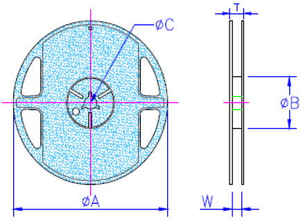
| Type | ΦA (mm) | ΦB (mm) | ΦC (mm) | W (mm) | T (mm) | Paper Tape (EA) | Emboss Plastic Tape (EA) |
|---|---|---|---|---|---|---|---|
| CSM02 | 178.0±1.0 | 60.0+1.0 | 13.5±0.7 | 9.5±0.1 | 11.5±1.0 | 10,000 | - |
| CSM03 | 178.0±1.0 | 60.0+1.0 | 13.5±0.7 | 9.5±0.1 | 11.5±1.0 | 5,000 | - |
| CSM05 | 178.0±1.0 | 60.0+1.0 | 13.5±0.7 | 9.5±0.1 | 11.5±1.0 | 5,000 | - |
| CSM06 | 178.0±1.0 | 60.0+1.0 | 13.5±0.7 | 9.5±0.1 | 11.5±1.0 | 5,000 | - |
| CSM10 | 178.0±1.0 | 60.0+1.0 | 13.5±0.7 | 13.5±1.0 | 15.5±1.0 | - | 4,000 |
| CSM12 | 178.0±1.0 | 60.0+1.0 | 13.5±0.7 | 13.5±1.0 | 15.5±1.0 | - | 4,000 |
Paper Tape Specifications
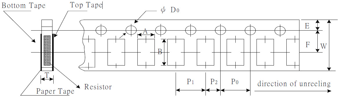
| Type | A (mm) | B (mm) | W (mm) | E (mm) | F (mm) | P0 (mm) | P1 (mm) | P2 (mm) | ΦD0 (mm) | T (mm) |
|---|---|---|---|---|---|---|---|---|---|---|
| CSM02 | 0.66±0.06 | 1.18±0.06 | 8.0±0.20 | 1.75±0.10 | 3.50±0.05 | 4.00±0.10 | 2.00±0.05 | 2.00±0.05 | 1.50±0.05 | 0.60±0.06 |
| CSM03 | 1.10±0.10 | 1.90±0.10 | 8.0±0.20 | 1.75±0.10 | 3.50±0.05 | 4.00±0.10 | 4.00±0.05 | 2.00±0.05 | 1.50+0.1,-0 | 0.70±0.10 |
| CSM03 (1/2W) |
1.10±0.10 | 1.85±0.10 | 8.0±0.20 | 1.75±0.10 | 3.50±0.05 | 4.00±0.10 | 4.00±0.05 | 2.00±0.05 | 1.50+0.1,-0 | 0.95±0.05 |
| CSM05 | 1.60±0.10 | 2.40±0.20 | 8.0±0.20 | 1.75±0.10 | 3.50±0.05 | 4.00±0.10 | 4.00±0.05 | 2.00±0.05 | 1.50+0.1,-0 | 0.85±0.10 |
| CSM05 (3/4W) |
1.65±0.10 | 2.35±0.20 | 8.0±0.20 | 1.75±0.10 | 3.50±0.05 | 4.00±0.10 | 4.00±0.05 | 2.00±0.05 | 1.50+0.1,-0 | 0.95±0.05 |
| CSM06 | 1.90±0.10 | 3.50±0.20 | 8.0±0.20 | 1.75±0.10 | 3.50±0.05 | 4.00±0.10 | 4.00±0.05 | 2.00±0.05 | 1.50+0.1,-0 | 0.85±0.10 |
| CSM06 (1W) |
1.90±0.10 | 3.50±0.20 | 8.0±0.20 | 1.75±0.10 | 3.50±0.05 | 4.00±0.10 | 4.00±0.05 | 2.00±0.05 | 1.50+0.1,-0 | 0.95±0.05 |
Emboss Plastic Tape Specifications
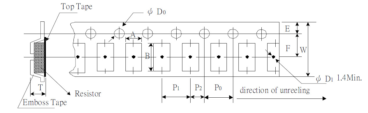
| Type | A (mm) | B (mm) | W (mm) | E (mm) | F (mm) | P0 (mm) | P1 (mm) | P2 (mm) | ΦD0 (mm) | T (mm) |
|---|---|---|---|---|---|---|---|---|---|---|
| CSM10 | 2.80±0.10 | 5.50±0.10 | 12.0±0.30 | 1.75±0.10 | 5.5±0.05 | 4.00±0.05 | 4.00±0.10 | 2.00±0.05 | 1.50+0.10 | 1.00±0.20 |
| CSM12 | 3.50±0.10 | 6.70±0.10 | 12.0±0.30 | 1.75±0.10 | 5.5±0.05 | 4.00±0.05 | 4.00±0.10 | 2.00±0.05 | 1.50+0.10 | 1.00±0.20 |

Resistore di precisione a film sottile 0,01%, TC2ppm, wirebondale, anti-corrosivo, MELF. Rilevamento...
Leggi di più
Induttori a chip in ceramica ad alta frequenza, dimensioni ridotte fino a 01005. Induttore a film sottile,...
Leggi di più
Il condensatore ceramico multistrato offre alta tensione, alta frequenza, basso rumore, alta Q, basso...
Leggi di più