25년 이상의 메탈 필름 고주파 MELF 저항기 (CSRF 시리즈) 제조업체 - Viking
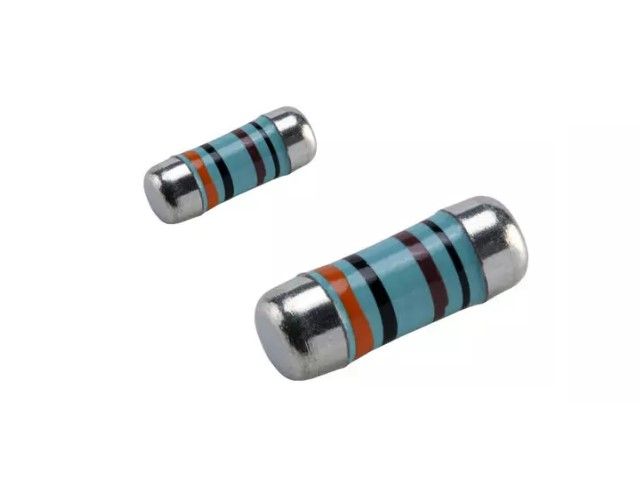
고주파 MELF 금속 필름 정밀 저항기, 0102/0204/0207 크기에 맞춰 준비되었습니다. 1%의 엄격한 허용오차, TC50ppm. 1.5옴~220옴. MELF는 원통형이며 금속 전극이 없는 면 저항기입니다. 토지 패턴 크기는 SMD 칩 저항기와 동일합니다. MELF 저항기의 높은 품질은 우수한 전기적 및 환경적 안정성을 제공하며, 수명, 편향 습도 및 단시간 과부하 테스트에서 입증된 뛰어난 안정성을 보여줍니다.Viking - IATF16949/ISO-9001/ISO-14001 인증을 받은 얇은/두꺼운 필름 공정 및 자동차, 전자 기기 응용을 위한 OEM 서비스. 코팅, 리소그래피, 얇은/두꺼운 필름 공정에 대한 맞춤 설계. 100% CCD 검사. 작은 크기와 가벼운 무게. IR 리플로우 납땜에 적합합니다. 20년 이상의 경험을 가진 Viking은 얇은 필름 칩 저항기, 칩 저항기, 전력 인덕터, 전류 감지 저항기, 두꺼운 필름 저항기, 칩 커패시터 및 세라믹 기판 제조를 전문으로 합니다.
0102 / 0204 / 0207 / Viking Tech는 혁신적인 부품 설계 경험을 보유하고 있으며, 진정한 제조 파트너를 요구하는 글로벌 고객에게 지원 및 서비스를 제공합니다. 우리의 목표는 자동차, 산업 및 3C 전자 응용 분야에서 사용되는 소형 정밀 수동 부품의 설계, 제조 및 마케팅에서 선두주자가 되는 것입니다.
고주파 MELF 금속 필름 정밀 저항기, 0102/0204/0207 크기에 맞춰 준비되었습니다. 1%의 엄격한 허용오차, TC50ppm. 1.5옴~220옴. MELF는 원통형이며 금속 전극이 없는 면 저항기입니다. 토지 패턴 크기는 SMD 칩 저항기와 동일합니다. MELF 저항기의 높은 품질은 우수한 전기적 및 환경적 안정성을 제공하며, 수명, 편향 습도 및 단시간 과부하 테스트에서 입증된 뛰어난 안정성을 보여줍니다.
기능
박막 기술
RF 응용에 적합
특수 트리밍 기술
니켈 장벽층의 Sn 종단
SMD 지원 구조.
무연 및 RoHS 준수.
응용 프로그램
산업
통신
구성
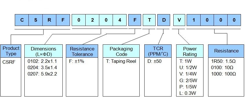
부품 번호 매기기
Part Number:CSRF0204FTDV1000
표준 전기 사양
Item Type
Power Rating
at 70°C
Operating Temp. Range
Max. Operating Voltage
Resistance Range
TCR (PPM/°C)
±1%(E24)
0102
0.2W \ 0.3W
-55 ~ +155°C
150V
50Ω, 6.8Ω-100Ω
±50
0204
1/4W \ 2/5W
-55 ~ +155°C
200V
50Ω, 1.5Ω-220Ω
±50
0207
1/2W \ 1W
-55 ~ +155°C
300V
50Ω, 6.8Ω-220Ω
±50
Operating Voltage=√(P*R) or Max. operating voltage listed above, whichever is lower.
Overload Voltage=2.5*√(P*R) or Max. overload voltage listed above, whichever is lower.
RCWV(Rated Continuous Working Voltage)=√(P*R) or Max. Operating Voltage whichever is lower.
☑ Viking is capable of manufacturing the optional spec based on customer's requirement.
펄스 내구성
The single impulse graph is the result of 50 impulses of rectangular shape applied at one-minute intervals. The limit of acceptance was a shift in resistance of less than 1% from the initial value. The power applied was subject to the restrictions of the maximum permissible impulse voltage graph shown.
연속 펄스
The continuous load graph was obtained by applying repetitive rectangular pulses where the pulse period was adjusted so that the average power dissipated in the resistor was equal to its rated power at 70°C. Again the limit of acceptance was a shift in resistance of less than 1% from the initial value.
번개 서지
Resistors are tested in accordance with IEC 60115-1 using both 1.2/50us and 10/700us pulse shapes. The limit of acceptance is a shift in resistance of less than 0.5% from the initial value.