
自動車アプリケーション
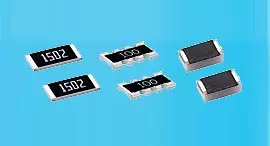
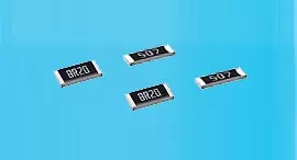
薄膜精密抵抗器0.01%、TC2ppm、ワイヤーボンダブル、防錆性、MELF。 電流センシング、金属、耐硫黄、サージ、高電圧、TO220/247パッケージ最大100Wまで
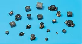
続きを読む台湾に本社を置くViking Tech Corporationは、1997年からの主要なワイヤー巻きチップインダクタ(フェライト)(NLシリーズ NL05JT120)メーカーの一つです。TS16949/ ISO9001/ ISO1400に準拠し、AEC-Q200基準を満たしており、製品は自動車や電子機器の用途に使用されています。Vikingは、薄膜/厚膜抵抗器、自動車用抵抗器、メルフ抵抗器、電流センス抵抗器を含む、耐硫黄、耐サージ、パルス、高電圧、高出力精密抵抗器を提供します。低ノイズ、低温度係数、高出力のインダクタ、例えばRFインダクタ、チップインダクタ、パワーインダクタ、可変インダクタ、フェライトチップインダクタ、シールドインダクタ、ワイヤー巻きインダクタ、ディップインダクタなどがあります。Vikingは、高品質のパワー抵抗器、パワーインダクタ、アルミ電解コンデンサを信頼性のある評判で顧客に提供してきました。20年以上の経験を持つVikingは、薄膜チップ抵抗器、チップ抵抗器、パワーインダクタ、電流センス抵抗器、厚膜抵抗器、チップコンデンサ、セラミック基板の製造を専門としています。
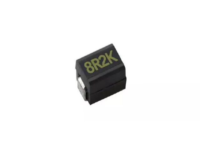
ワイヤー巻きチップフェライトインダクタ、高電流、成形タイプとオープンタイプが利用可能です。0603サイズまでの小型で、フローはんだ付けやはんだごて、波はんだ付けによる非常に強いはんだ付け性を持っています。機械的衝撃や圧力に対して非常に耐性があります。急激な温度変化や湿度の環境でも非常に信頼性があります。スーパーQ特性。
NL Series0805 ±5% 12μH 2.8 Ω 220mA 16 37
| サイズ | 公差 | インダクタンス | 試験条件 | DCR (Ω) 最大 | IDC (mA) | Q | SRF |
|---|---|---|---|---|---|---|---|
| 0805 | ±5% | 12 | 2.5MHz | 2.8 | 220 | 16 | 37 |
NL03 Wound Chip Inductors (Ferrite / Open Type) / Large Current Type
| Codes | Inductance (uH) | Tolerance | Q min. | Test Freq. (MHz) | SRF (MHz) min. | DCR (Ω) max. | IDC (mA) max. | Color Code |
|---|---|---|---|---|---|---|---|---|
| R10 | 0.10 | ± 5, ± 10, ± 20% | 12 | 7.9 | 1150 | 0.13 | 1700 | Black |
| R12 | 0.12 | ± 5, ± 10, ± 20% | 12 | 7.9 | 1100 | 0.15 | 1700 | Orange |
| R15 | 0.15 | ± 5, ± 10, ± 20% | 15 | 7.9 | 1050 | 0.15 | 1600 | Brown |
| R18 | 0.18 | ± 5, ± 10, ± 20% | 15 | 7.9 | 950 | 0.15 | 1500 | Green |
| R22 | 0.22 | ± 5, ± 10, ± 20% | 15 | 7.9 | 900 | 0.30 | 1200 | Red |
| R24 | 0.24 | ± 5, ± 10, ± 20% | 15 | 7.9 | 850 | 0.16 | 1460 | Green |
| R27 | 0.27 | ± 5, ± 10, ± 20% | 15 | 7.9 | 835 | 0.30 | 1460 | Yellow |
| R33 | 0.33 | ± 5, ± 10, ± 20% | 15 | 7.9 | 725 | 0.40 | 1420 | Orange |
| R39 | 0.39 | ± 5, ± 10, ± 20% | 15 | 7.9 | 680 | 0.41 | 1400 | Blue |
| R47 | 0.47 | ± 5, ± 10, ± 20% | 15 | 7.9 | 640 | 0.43 | 1400 | Black |
| R56 | 0.56 | ± 5, ± 10, ± 20% | 15 | 7.9 | 630 | 0.44 | 1400 | Brown |
| R68 | 0.68 | ± 5, ± 10, ± 20% | 15 | 7.9 | 510 | 0.52 | 1340 | Red |
| R78 | 0.78 | ± 5, ± 10, ± 20% | 15 | 7.9 | 465 | 0.63 | 1300 | Orange |
| R82 | 0.82 | ± 5, ± 10, ± 20% | 15 | 7.9 | 460 | 0.69 | 1200 | Yellow |
| 1R0 | 1.0 | ± 5, ± 10, ± 20% | 15 | 7.9 | 320 | 0.81 | 1100 | Green |
| 1R2 | 1.2 | ± 5, ± 10, ± 20% | 15 | 7.9 | 270 | 0.87 | 1100 | Blue |
| 1R5 | 1.5 | ± 5, ± 10, ± 20% | 15 | 7.9 | 230 | 0.96 | 920 | Violet |
| 1R8 | 1.8 | ± 5, ± 10, ± 20% | 15 | 7.9 | 210 | 1.10 | 900 | Gray |
| 2R2 | 2.2 | ± 5, ± 10, ± 20% | 15 | 7.9 | 115 | 1.20 | 740 | White |
| 2R7 | 2.7 | ± 5, ± 10, ± 20% | 15 | 7.9 | 100 | 1.38 | 700 | Black |
| 3R3 | 3.3 | ± 5, ± 10, ± 20% | 15 | 7.9 | 84 | 1.50 | 680 | Brown |
| 3R9 | 3.9 | ± 5, ± 10, ± 20% | 15 | 7.9 | 75 | 1.50 | 600 | Red |
| 4R7 | 4.7 | ± 5, ± 10, ± 20% | 15 | 7.9 | 67 | 2.10 | 580 | Orange |
| 5R6 | 5.6 | ± 5, ± 10, ± 20% | 15 | 7.9 | 55 | 2.37 | 540 | Yellow |
| 6R8 | 6.8 | ± 5, ± 10, ± 20% | 15 | 7.9 | 48 | 3.10 | 500 | Green |
| 7R8 | 7.8 | ± 5, ± 10, ± 20% | 15 | 7.9 | 40 | 3.35 | 460 | Blue |
| 8R2 | 8.2 | ± 5, ± 10, ± 20% | 15 | 7.9 | 38 | 3.50 | 440 | Violet |
| 100 | 10 | ± 5, ± 10, ± 20% | 15 | 7.9 | 32 | 4.46 | 400 | Gray |
NL05 Wire Wound Chip Inductors (Ferrite / Open Type) / Large Current Type
| Codes | Inductance (uH) | Tolerance | Q typ. | Test Freq. (MHz) | SRF (MHz) typ. | DCR (Ω) max. | IDC (mA) typ. | Color Code |
|---|---|---|---|---|---|---|---|---|
| R47 | 0.47 | ± 5, ± 10, ± 20% | 14 | 7.9 | 850 | 0.156 | 1400 | Blue |
| R68 | 0.68 | ± 5, ± 10, ± 20% | 14 | 7.9 | 765 | 0.195 | 1200 | Gray |
| 1R0 | 1.00 | ± 5, ± 10, ± 20% | 14 | 7.9 | 208 | 0.169 | 1100 | Black |
| 1R2 | 1.20 | ± 5, ± 10, ± 20% | 14 | 7.9 | 159 | 0.208 | 960 | Red |
| 1R5 | 1.50 | ± 5, ± 10, ± 20% | 14 | 7.9 | 159 | 0.221 | 920 | Brown |
| 1R8 | 1.80 | ± 5, ± 10, ± 20% | 14 | 7.9 | 112 | 0.260 | 860 | Orange |
| 2R2 | 2.20 | ± 5, ± 10, ± 20% | 13 | 7.9 | 87 | 0.286 | 740 | Red |
| 2R7 | 2.70 | ± 5, ± 10, ± 20% | 13 | 7.9 | 72 | 0.325 | 680 | Yellow |
| 3R3 | 3.30 | ± 5, ± 10, ± 20% | 12 | 7.9 | 70 | 0.364 | 620 | Orange |
| 3R9 | 3.90 | ± 5, ± 10, ± 20% | 14 | 7.9 | 61 | 0.494 | 580 | Green |
| 4R7 | 4.70 | ± 5, ± 10, ± 20% | 14 | 7.9 | 51 | 0.559 | 520 | Yellow |
| 5R6 | 5.60 | ± 5, ± 10, ± 20% | 12 | 7.9 | 47 | 0.650 | 480 | Blue |
| 6R8 | 6.80 | ± 5, ± 10, ± 20% | 14 | 7.9 | 46 | 0.884 | 420 | Green |
| 8R2 | 8.20 | ± 5, ± 10, ± 20% | 13 | 7.9 | 33 | 0.949 | 400 | Violet |
| 100 | 10 | ± 5, ± 10, ± 20% | 14 | 2.5 | 31 | 1.105 | 360 | Blue |
| 120 | 12 | ± 5, ± 10, ± 20% | 14 | 2.5 | 30 | 1.17 | 340 | Gray |
| 150 | 15 | ± 5, ± 10, ± 20% | 15 | 2.5 | 28 | 1.82 | 300 | Violet |
| 180 | 18 | ± 5, ± 10, ± 20% | 15 | 2.5 | 27 | 2.01 | 280 | White |
| 220 | 22 | ± 5, ± 10, ± 20% | 15 | 2.5 | 20 | 2.288 | 240 | Gray |
| 270 | 27 | ± 5, ± 10, ± 20% | 15 | 2.5 | 17 | 2.60 | 220 | Black |
| 330 | 33 | ± 5, ± 10, ± 20% | 15 | 2.5 | 17 | 3.055 | 200 | White |
| 470 | 47 | ± 5, ± 10, ± 20% | 14 | 2.5 | 15 | 4.42 | 160 | Black |
| 560 | 56 | ± 5, ± 10, ± 20% | 14 | 2.5 | 10 | 5.746 | 150 | Yellow |
| 680 | 68 | ± 5, ± 10, ± 20% | 14 | 2.5 | 10 | 5.785 | 140 | Brown |
| 820 | 82 | ± 5, ± 10, ± 20% | 14 | 2.5 | 10 | 9.75 | 100 | Orange |
| 101 | 100 | ± 5, ± 10, ± 20% | 10 | 1 | 9 | 9.75 | 100 | Red |
NL10 Wire Wound Chip Inductors (Ferrite / Molding Type) / Large Current Type
| Codes | Inductance (uH) | Tolerance | Q min. | Test Freq. (MHz) | SRF (MHz) typ. | DCR (Ω) max. | IDC (mA) max. |
|---|---|---|---|---|---|---|---|
| 1R0 | 1.0 | ± 5%,± 20% | 10 | 7.96 | 145 | 0.156 | 770 |
| 1R5 | 1.5 | ± 5%,± 20% | 10 | 7.96 | 100 | 0.195 | 580 |
| 2R2 | 2.2 | ± 5%,± 20% | 10 | 7.96 | 80 | 0.260 | 480 |
| 3R3 | 3.3 | ± 5%,± 20% | 10 | 7.96 | 60 | 0.325 | 400 |
| 4R7 | 4.7 | ± 5%,± 20% | 10 | 7.96 | 50 | 0.520 | 320 |
| 6R8 | 6.8 | ± 5%,± 20% | 10 | 7.96 | 40 | 0.650 | 280 |
| 100 | 10 | ± 5%,± 10% | 15 | 2.52 | 30 | 1.105 | 220 |
| 150 | 15 | ± 5%,± 10% | 15 | 2.52 | 27 | 1.690 | 180 |
| 220 | 22 | ± 5%,± 10% | 15 | 2.52 | 22 | 2.600 | 145 |
| 270 | 27 | ± 5%,± 10% | 15 | 2.52 | 19 | 3.000 | 125 |
| 330 | 33 | ± 5%,± 10% | 15 | 2.52 | 17 | 3.640 | 115 |
| 470 | 47 | ± 5%,± 10% | 20 | 2.52 | 15 | 5.460 | 105 |
| 680 | 68 | ± 5%,± 10% | 20 | 2.52 | 11 | 8.450 | 85 |
| 820 | 82 | ± 5%,± 10% | 20 | 2.52 | 10 | 8.710 | 80 |
| 101 | 100 | ± 5%,± 10% | 20 | 0.796 | 9 | 10.140 | 75 |
NL12 Wire Wound Chip Inductors (Ferrite / Molding Type) / Large Current Type
| Codes | Inductance (uH) | Tolerance | Q min. | Test Freq. (MHz) | SRF (MHz) typ. | DCR (Ω) max. | IDC (mA) max. |
|---|---|---|---|---|---|---|---|
| 1R0 | 1.0 | ± 5%,± 10% | 10 | 7.96 | 265 | 0.11 | 1050 |
| 1R2 | 1.2 | ± 5%,± 10% | 10 | 7.96 | 180 | 0.12 | 1000 |
| 1R5 | 1.5 | ± 5%,± 10% | 10 | 7.96 | 170 | 0.15 | 950 |
| 1R8 | 1.8 | ± 5%,± 10% | 10 | 7.96 | 105 | 0.16 | 900 |
| 2R2 | 2.2 | ± 5%,± 10% | 10 | 7.96 | 80 | 0.18 | 850 |
| 2R7 | 2.7 | ± 5%,± 10% | 10 | 7.96 | 60 | 0.20 | 800 |
| 3R3 | 3.3 | ± 5%,± 10% | 10 | 7.96 | 55 | 0.22 | 750 |
| 3R9 | 3.9 | ± 5%,± 10% | 10 | 7.96 | 45 | 0.24 | 700 |
| 4R7 | 4.7 | ± 5%,± 10% | 10 | 7.96 | 43 | 0.27 | 650 |
| 5R6 | 5.6 | ± 5%,± 10% | 10 | 7.96 | 40 | 0.30 | 650 |
| 6R8 | 6.8 | ± 5%,± 10% | 10 | 7.96 | 35 | 0.35 | 600 |
| 8R2 | 8.2 | ± 5%,± 10% | 10 | 7.96 | 30 | 0.40 | 600 |
| 100 | 10 | ± 5%,± 10% | 10 | 2.52 | 27 | 0.50 | 550 |
| 120 | 12 | ± 5%,± 10% | 10 | 2.52 | 25 | 0.60 | 500 |
| 150 | 15 | ± 5%,± 10% | 10 | 2.52 | 20 | 0.70 | 450 |
| 180 | 18 | ± 5%,± 10% | 10 | 2.52 | 19 | 0.80 | 400 |
| 220 | 22 | ± 5%,± 10% | 10 | 2.52 | 18 | 0.90 | 370 |
| 270 | 27 | ± 5%,± 10% | 10 | 2.52 | 16 | 1.20 | 330 |
| 330 | 33 | ± 5%,± 10% | 10 | 2.52 | 15 | 1.40 | 300 |
| 390 | 39 | ± 5%,± 10% | 10 | 2.52 | 13 | 1.60 | 280 |
| 470 | 47 | ± 5%,± 10% | 10 | 2.52 | 12 | 1.90 | 260 |
| 560 | 56 | ± 5%,± 10% | 10 | 2.52 | 10 | 2.20 | 240 |
| 680 | 68 | ± 5%,± 10% | 10 | 2.52 | 9.5 | 2.60 | 220 |
| 820 | 82 | ± 5%,± 10% | 10 | 2.52 | 8.5 | 3.50 | 200 |
| 101 | 100 | ± 5%,± 10% | 20 | 0.796 | 8.0 | 4.00 | 180 |
| 121 | 120 | ± 5%,± 10% | 20 | 0.796 | 7.0 | 4.50 | 160 |
| 151 | 150 | ± 5%,± 10% | 20 | 0.796 | 6.5 | 6.50 | 140 |
| 181 | 180 | ± 5%,± 10% | 20 | 0.796 | 6.0 | 7.50 | 120 |
| 221 | 220 | ± 5%,± 10% | 20 | 0.796 | 5.5 | 9.00 | 120 |
| 271 | 270 | ± 5%,± 10% | 20 | 0.796 | 5.0 | 11.0 | 100 |
| 331 | 330 | ± 5%,± 10% | 20 | 0.796 | 4.5 | 13.0 | 90 |
| 391 | 390 | ± 5%,± 10% | 20 | 0.796 | 4.0 | 14.0 | 85 |
| 471 | 470 | ± 5%,± 10% | 20 | 0.796 | 3.5 | 16.0 | 75 |
| 561 | 560 | ± 5%,± 10% | 20 | 0.796 | 3.0 | 21.0 | 70 |
| 681 | 680 | ± 5%,± 10% | 20 | 0.796 | 2.5 | 24.0 | 65 |
NL20 Wire Wound Chip Inductors (Ferrite / Molding Type) / Large Current Type
| Codes | Inductance (uH) | Tolerance | Q min. | Test Freq. (MHz) | SRF (MHz) min. | DCR (Ω) max. | IDC (mA) max. |
|---|---|---|---|---|---|---|---|
| 1R0 | 1.0 | ± 10,± 20% | 10 | 7.96 | 95 | 0.03 | 1800 |
| 1R2 | 1.2 | ± 10, ± 20% | 10 | 7.96 | 70 | 0.035 | 1700 |
| 1R5 | 1.5 | ± 10, ± 20% | 10 | 7.96 | 55 | 0.04 | 1600 |
| 1R8 | 1.8 | ± 10, ± 20% | 10 | 7.96 | 47 | 0.05 | 1400 |
| 2R2 | 2.2 | ± 10, ± 20% | 10 | 7.96 | 42 | 0.06 | 1300 |
| 2R7 | 2.7 | ± 10, ± 20% | 10 | 7.96 | 37 | 0.07 | 1200 |
| 3R3 | 3.3 | ± 10, ± 20% | 10 | 7.96 | 34 | 0.08 | 1120 |
| 3R9 | 3.9 | ± 10, ± 20% | 10 | 7.96 | 32 | 0.09 | 1050 |
| 4R7 | 4.7 | ± 10, ± 20% | 10 | 7.96 | 29 | 0.11 | 950 |
| 5R6 | 5.6 | ± 10, ± 20% | 10 | 7.96 | 26 | 0.13 | 880 |
| 6R8 | 6.8 | ± 10, ± 20% | 10 | 7.96 | 24 | 0.15 | 810 |
| 8R2 | 8.2 | ± 10, ± 20% | 10 | 7.96 | 22 | 0.18 | 750 |
| 100 | 10 | ± 10, ± 20% | 10 | 2.52 | 19 | 0.21 | 690 |
| 120 | 12 | ± 10, ± 20% | 10 | 2.52 | 17 | 0.25 | 630 |
| 150 | 15 | ± 10, ± 20% | 10 | 2.52 | 16 | 0.30 | 580 |
| 180 | 18 | ± 10, ± 20% | 10 | 2.52 | 14 | 0.36 | 530 |
| 220 | 22 | ± 5, ± 10% | 10 | 2.52 | 13 | 0.43 | 480 |
| 270 | 27 | ± 5, ± 10% | 10 | 2.52 | 11.5 | 0.52 | 440 |
| 330 | 33 | ± 5, ± 10% | 10 | 2.52 | 10.5 | 0.62 | 400 |
| 390 | 39 | ± 5, ± 10% | 10 | 2.52 | 9.5 | 0.72 | 370 |
| 470 | 47 | ± 5, ± 10% | 10 | 2.52 | 8.5 | 0.85 | 340 |
| 560 | 56 | ± 5, ± 10% | 10 | 2.52 | 7.8 | 1.00 | 310 |
| 680 | 68 | ± 5, ± 10% | 10 | 2.52 | 7.0 | 1.2 | 290 |
| 820 | 82 | ± 5, ± 10% | 10 | 2.52 | 6.4 | 1.4 | 270 |
| 101 | 100 | ± 5, ± 10% | 20 | 0.796 | 6.0 | 1.6 | 250 |
| 121 | 120 | ± 5, ± 10% | 20 | 0.796 | 5.4 | 1.9 | 230 |
| 151 | 150 | ± 5, ± 10% | 20 | 0.796 | 4.8 | 2.2 | 210 |
| 181 | 180 | ± 5, ± 10% | 20 | 0.796 | 4.4 | 2.8 | 190 |
| 221 | 220 | ± 5, ± 10% | 20 | 0.796 | 3.9 | 3.4 | 170 |
| 271 | 270 | ± 5, ± 10% | 20 | 0.796 | 3.6 | 4.2 | 155 |
| 331 | 330 | ± 5, ± 10% | 20 | 0.796 | 3.2 | 4.9 | 140 |
| 391 | 390 | ± 5, ± 10% | 20 | 0.796 | 2.9 | 5.8 | 130 |
| 471 | 470 | ± 5, ± 10% | 20 | 0.796 | 2.6 | 7.0 | 120 |
| 561 | 560 | ± 5, ± 10% | 20 | 0.796 | 2.4 | 8.5 | 110 |
| 681 | 680 | ± 5, ± 10% | 20 | 0.796 | 2.2 | 10 | 100 |
| 821 | 820 | ± 5, ± 10% | 20 | 0.796 | 2.0 | 13 | 90 |
| 102 | 1000 | ± 5, ± 10% | 20 | 0.252 | 1.8 | 15 | 85 |
Electrical Performance Test
| Item | Requirement | Test Method |
|---|---|---|
| Inductance | Refer to standard electrical characteristic spec. | HP4291 or HP4284 |
| Q | HP4291 or HP4284 | |
| SRF | HP4291 | |
| DC Resistance DCR | Agilent 34401A | |
| Rated Current IDC | Applied the current to coils, The inductance change should be less than 10% to initial value. |
Mechanical Performance Test
| Item | Requirement | Test Method |
|---|---|---|
| Solderability | The electrodes shall be at least 90% covered with new solder coating | Lead-free inductor: after fluxing (alpha 100 or equiv), inductor shall be dipped in a melted solder bath at 245 ± 5°C, 5 ± 0.5 seconds |
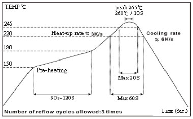
| Resistance to Soldering Heat | Appearance: No damage | Pre-heating: 150°C, 1min. Solder Temperature: 260 ± 5°C Immersion Time: 10 ± 1 seconds |
| Vibration | Appearance: No damage L change: within ± 10% Q change: within ± 30% DCR: within specification |
Test device shall be soldered on the substrate Oscillation Frequency: 10 to 55 to 10Hz for 1 min. Amplitude: 1.5 mm Time: 2 hrs for each axis (X, Y & Z), total 6 hrs |
Climatic Test
| Item | Requirement | Test Method | |||||||||||||||
|---|---|---|---|---|---|---|---|---|---|---|---|---|---|---|---|---|---|
| Temperature Cycle | Appearance: No damage L change: within ± 10% Q change: within ± 30% DCR: within specification |
One cycle:
Total: 100 cycles |
|||||||||||||||
| Damp Heat with Load | Temperature: 40 ± 2°C Relative Humidity: 90 ~ 95% Time: 1000 hrs Measured after exposure in the room condition for 24 hrs |
||||||||||||||||
| High Temperature Storage | Temperature: 85 ± 3°C Applied Current: Rated Current Time: 1000 hrs Measured after exposure in the room condition for 24 hrs |
||||||||||||||||
| Low Temperature Storage | Temperature: -25 ± 3°C Time: 1000 hrs Measured after exposure in the room condition for 24 hrs |
☑ Storage Temperature: 15 ~ 28°C; Humidity < 80%RH
☑ Operating Temperature Range: -40 ~ +85°C
Packaging Quantity & Reel Specifications (Unit : mm)
| Type | Ø A | Ø B | Ø C | W | T | Quantity (EA) | 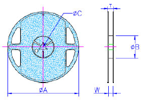 |
|---|---|---|---|---|---|---|---|
| NL03 | 178 ± 2.0 | 60 ± 0.5 | 13 ± 0.3 | 9 ± 0.3 | 12 ± 1.0 | 4000 | |
| NL05 | 178 ± 2.0 | 60 ± 0.5 | 13 ± 0.3 | 9 ± 0.3 | 12 ± 1.0 | 2000 | |
| NL08 | 178 ± 2.0 | 60 ± 0.5 | 13 ± 0.3 | 9 ± 0.3 | 12 ± 1.0 | 2000 | |
| NL10 | 178 ± 2.0 | 60 ± 0.5 | 13 ± 0.3 | 9 ± 0.3 | 12 ± 1.0 | 2000 | |
| NL12 | 178 ± 2.0 | 80 ± 0.5 | 13 ± 0.3 | 13.2 ± 0.3 | 16 ± 1.0 | 500 | |
| NL20 | 330 ± 2.0 | 100 ± 0.5 | 13 ± 0.3 | 17.4 ± 0.3 | 22 ± 1.0 | 1000 |
Embossed Plastic Tape Specifications (Unit : mm)
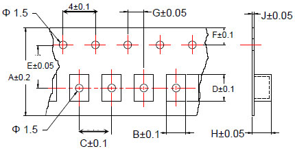
| Type | A | B | C | D | E | F | G | H | J |
|---|---|---|---|---|---|---|---|---|---|
| NL03 | 8 | 1.25 | 4 | 1.90 | 3.5 | 1.75 | 2 | 1.00 | 0.23 |
| NL05 | 8 | 1.85 | 4 | 2.55 | 3.5 | 1.75 | 2 | 1.45 | 0.23 |
| NL08 | 8 | 2.80 | 4 | 2.95 | 3.5 | 1.75 | 2 | 2.22 | 0.23 |
| NL10 | 8 | 2.96 | 4 | 3.60 | 3.5 | 1.75 | 2 | 2.40 | 0.23 |
| NL12 | 12 | 3.30 | 8 | 5.00 | 5.5 | 1.75 | 2 | 3.50 | 0.30 |
| NL20 | 16 | 5.35 | 12 | 6.10 | 7.5 | 1.75 | 2 | 5.50 | 0.35 |
Leader / Trailer Tape
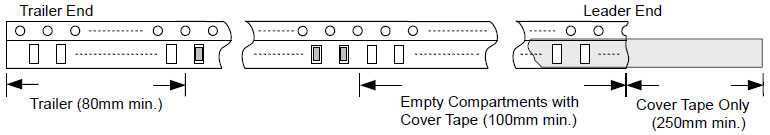
Cover Tape Peel Strength
The force for tearing off cover tape is 0.1 ~ 0.6 (N) in the arrow direction at the following conditions: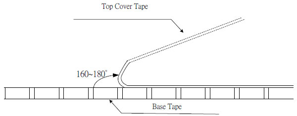

薄膜精密抵抗器0.01%、TC2ppm、ワイヤーボンダブル、防錆性、MELF。 電流センシング、金属、耐硫黄、サージ、高電圧、TO220/247パッケージ最大100Wまで
続きを読む