
AUTOMOTIVE APPLICATIONS
Thin film Precision resistor 0.01%, TC2ppm, wirebondale, Anti-Crossive, MELF. Current sensing, Metal...
Read MoreBased in Taiwan, Viking Tech Corporation is one of the prime Wire Wound Chip Inductor(Ferrite) (NL Series NL05JTR33) manufacturers since 1997. TS16949/ ISO9001/ ISO1400, meet AEC-Q200 standards, and the products are used for automotive, electronic device applications. Viking provides anti-sulfur, anti-surge, pulse, high voltage, high power precision resistors including thin/ thick film resistors, automotive resistors, melf resistors, current sense resistors. Low noise, low TC, high power inductors such as rf inductors, chip inductors, power inductors, variable inductors, ferrite chip inductors, shielded inductors, wire wound inductors and dip inductors. Viking has been offering customers high quality power resistors, power inductors and aluminum electrolytic capacitors with solid reputation. With more than 20 years experience, Viking is specialized in manufacturing Thin Film Chip Resistor, Chip Resistor, Power Inductor, Current Sense Resistor, Thick Film Resistor, Chip Capacitor and Ceramic Substrate.
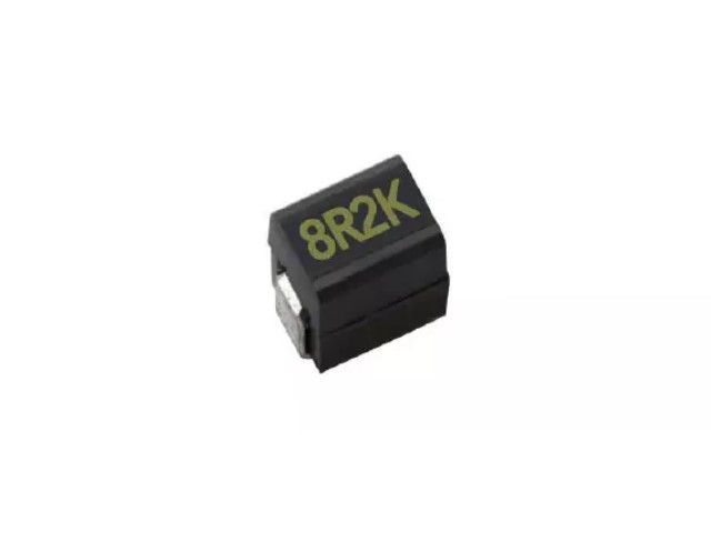
Wire wound chip ferrite inductor, high current, molded and open type are available. small size down to 0603 , very strong solderability by flow soldering or soldering iron , wave soldering. Highly resistanct to mechanical shocks and pressure. Highly reliable in environments of sudden temp change and humidity. super Q characteristics.
NL Series0805 ±5% 0.33μH 0.35 Ω 1200mA 30 750
| Size | Tolerance | Inductance | Test Condition | DCR (Ω) max. | IDC (mA) | Q | SRF |
|---|---|---|---|---|---|---|---|
| 0805 | ±5% | 0.33 | 25MHz | 0.35 | 1200 | 30 | 750 |
NL03 Wound Chip Inductors (Ferrite / Open Type) / Large Current Type
| Codes | Inductance (uH) | Tolerance | Q min. | Test Freq. (MHz) | SRF (MHz) min. | DCR (Ω) max. | IDC (mA) max. | Color Code |
|---|---|---|---|---|---|---|---|---|
| R10 | 0.10 | ± 5, ± 10, ± 20% | 12 | 7.9 | 1150 | 0.13 | 1700 | Black |
| R12 | 0.12 | ± 5, ± 10, ± 20% | 12 | 7.9 | 1100 | 0.15 | 1700 | Orange |
| R15 | 0.15 | ± 5, ± 10, ± 20% | 15 | 7.9 | 1050 | 0.15 | 1600 | Brown |
| R18 | 0.18 | ± 5, ± 10, ± 20% | 15 | 7.9 | 950 | 0.15 | 1500 | Green |
| R22 | 0.22 | ± 5, ± 10, ± 20% | 15 | 7.9 | 900 | 0.30 | 1200 | Red |
| R24 | 0.24 | ± 5, ± 10, ± 20% | 15 | 7.9 | 850 | 0.16 | 1460 | Green |
| R27 | 0.27 | ± 5, ± 10, ± 20% | 15 | 7.9 | 835 | 0.30 | 1460 | Yellow |
| R33 | 0.33 | ± 5, ± 10, ± 20% | 15 | 7.9 | 725 | 0.40 | 1420 | Orange |
| R39 | 0.39 | ± 5, ± 10, ± 20% | 15 | 7.9 | 680 | 0.41 | 1400 | Blue |
| R47 | 0.47 | ± 5, ± 10, ± 20% | 15 | 7.9 | 640 | 0.43 | 1400 | Black |
| R56 | 0.56 | ± 5, ± 10, ± 20% | 15 | 7.9 | 630 | 0.44 | 1400 | Brown |
| R68 | 0.68 | ± 5, ± 10, ± 20% | 15 | 7.9 | 510 | 0.52 | 1340 | Red |
| R78 | 0.78 | ± 5, ± 10, ± 20% | 15 | 7.9 | 465 | 0.63 | 1300 | Orange |
| R82 | 0.82 | ± 5, ± 10, ± 20% | 15 | 7.9 | 460 | 0.69 | 1200 | Yellow |
| 1R0 | 1.0 | ± 5, ± 10, ± 20% | 15 | 7.9 | 320 | 0.81 | 1100 | Green |
| 1R2 | 1.2 | ± 5, ± 10, ± 20% | 15 | 7.9 | 270 | 0.87 | 1100 | Blue |
| 1R5 | 1.5 | ± 5, ± 10, ± 20% | 15 | 7.9 | 230 | 0.96 | 920 | Violet |
| 1R8 | 1.8 | ± 5, ± 10, ± 20% | 15 | 7.9 | 210 | 1.10 | 900 | Gray |
| 2R2 | 2.2 | ± 5, ± 10, ± 20% | 15 | 7.9 | 115 | 1.20 | 740 | White |
| 2R7 | 2.7 | ± 5, ± 10, ± 20% | 15 | 7.9 | 100 | 1.38 | 700 | Black |
| 3R3 | 3.3 | ± 5, ± 10, ± 20% | 15 | 7.9 | 84 | 1.50 | 680 | Brown |
| 3R9 | 3.9 | ± 5, ± 10, ± 20% | 15 | 7.9 | 75 | 1.50 | 600 | Red |
| 4R7 | 4.7 | ± 5, ± 10, ± 20% | 15 | 7.9 | 67 | 2.10 | 580 | Orange |
| 5R6 | 5.6 | ± 5, ± 10, ± 20% | 15 | 7.9 | 55 | 2.37 | 540 | Yellow |
| 6R8 | 6.8 | ± 5, ± 10, ± 20% | 15 | 7.9 | 48 | 3.10 | 500 | Green |
| 7R8 | 7.8 | ± 5, ± 10, ± 20% | 15 | 7.9 | 40 | 3.35 | 460 | Blue |
| 8R2 | 8.2 | ± 5, ± 10, ± 20% | 15 | 7.9 | 38 | 3.50 | 440 | Violet |
| 100 | 10 | ± 5, ± 10, ± 20% | 15 | 7.9 | 32 | 4.46 | 400 | Gray |
NL05 Wire Wound Chip Inductors (Ferrite / Open Type) / Large Current Type
| Codes | Inductance (uH) | Tolerance | Q typ. | Test Freq. (MHz) | SRF (MHz) typ. | DCR (Ω) max. | IDC (mA) typ. | Color Code |
|---|---|---|---|---|---|---|---|---|
| R47 | 0.47 | ± 5, ± 10, ± 20% | 14 | 7.9 | 850 | 0.156 | 1400 | Blue |
| R68 | 0.68 | ± 5, ± 10, ± 20% | 14 | 7.9 | 765 | 0.195 | 1200 | Gray |
| 1R0 | 1.00 | ± 5, ± 10, ± 20% | 14 | 7.9 | 208 | 0.169 | 1100 | Black |
| 1R2 | 1.20 | ± 5, ± 10, ± 20% | 14 | 7.9 | 159 | 0.208 | 960 | Red |
| 1R5 | 1.50 | ± 5, ± 10, ± 20% | 14 | 7.9 | 159 | 0.221 | 920 | Brown |
| 1R8 | 1.80 | ± 5, ± 10, ± 20% | 14 | 7.9 | 112 | 0.260 | 860 | Orange |
| 2R2 | 2.20 | ± 5, ± 10, ± 20% | 13 | 7.9 | 87 | 0.286 | 740 | Red |
| 2R7 | 2.70 | ± 5, ± 10, ± 20% | 13 | 7.9 | 72 | 0.325 | 680 | Yellow |
| 3R3 | 3.30 | ± 5, ± 10, ± 20% | 12 | 7.9 | 70 | 0.364 | 620 | Orange |
| 3R9 | 3.90 | ± 5, ± 10, ± 20% | 14 | 7.9 | 61 | 0.494 | 580 | Green |
| 4R7 | 4.70 | ± 5, ± 10, ± 20% | 14 | 7.9 | 51 | 0.559 | 520 | Yellow |
| 5R6 | 5.60 | ± 5, ± 10, ± 20% | 12 | 7.9 | 47 | 0.650 | 480 | Blue |
| 6R8 | 6.80 | ± 5, ± 10, ± 20% | 14 | 7.9 | 46 | 0.884 | 420 | Green |
| 8R2 | 8.20 | ± 5, ± 10, ± 20% | 13 | 7.9 | 33 | 0.949 | 400 | Violet |
| 100 | 10 | ± 5, ± 10, ± 20% | 14 | 2.5 | 31 | 1.105 | 360 | Blue |
| 120 | 12 | ± 5, ± 10, ± 20% | 14 | 2.5 | 30 | 1.17 | 340 | Gray |
| 150 | 15 | ± 5, ± 10, ± 20% | 15 | 2.5 | 28 | 1.82 | 300 | Violet |
| 180 | 18 | ± 5, ± 10, ± 20% | 15 | 2.5 | 27 | 2.01 | 280 | White |
| 220 | 22 | ± 5, ± 10, ± 20% | 15 | 2.5 | 20 | 2.288 | 240 | Gray |
| 270 | 27 | ± 5, ± 10, ± 20% | 15 | 2.5 | 17 | 2.60 | 220 | Black |
| 330 | 33 | ± 5, ± 10, ± 20% | 15 | 2.5 | 17 | 3.055 | 200 | White |
| 470 | 47 | ± 5, ± 10, ± 20% | 14 | 2.5 | 15 | 4.42 | 160 | Black |
| 560 | 56 | ± 5, ± 10, ± 20% | 14 | 2.5 | 10 | 5.746 | 150 | Yellow |
| 680 | 68 | ± 5, ± 10, ± 20% | 14 | 2.5 | 10 | 5.785 | 140 | Brown |
| 820 | 82 | ± 5, ± 10, ± 20% | 14 | 2.5 | 10 | 9.75 | 100 | Orange |
| 101 | 100 | ± 5, ± 10, ± 20% | 10 | 1 | 9 | 9.75 | 100 | Red |
NL10 Wire Wound Chip Inductors (Ferrite / Molding Type) / Large Current Type
| Codes | Inductance (uH) | Tolerance | Q min. | Test Freq. (MHz) | SRF (MHz) typ. | DCR (Ω) max. | IDC (mA) max. |
|---|---|---|---|---|---|---|---|
| 1R0 | 1.0 | ± 5%,± 20% | 10 | 7.96 | 145 | 0.156 | 770 |
| 1R5 | 1.5 | ± 5%,± 20% | 10 | 7.96 | 100 | 0.195 | 580 |
| 2R2 | 2.2 | ± 5%,± 20% | 10 | 7.96 | 80 | 0.260 | 480 |
| 3R3 | 3.3 | ± 5%,± 20% | 10 | 7.96 | 60 | 0.325 | 400 |
| 4R7 | 4.7 | ± 5%,± 20% | 10 | 7.96 | 50 | 0.520 | 320 |
| 6R8 | 6.8 | ± 5%,± 20% | 10 | 7.96 | 40 | 0.650 | 280 |
| 100 | 10 | ± 5%,± 10% | 15 | 2.52 | 30 | 1.105 | 220 |
| 150 | 15 | ± 5%,± 10% | 15 | 2.52 | 27 | 1.690 | 180 |
| 220 | 22 | ± 5%,± 10% | 15 | 2.52 | 22 | 2.600 | 145 |
| 270 | 27 | ± 5%,± 10% | 15 | 2.52 | 19 | 3.000 | 125 |
| 330 | 33 | ± 5%,± 10% | 15 | 2.52 | 17 | 3.640 | 115 |
| 470 | 47 | ± 5%,± 10% | 20 | 2.52 | 15 | 5.460 | 105 |
| 680 | 68 | ± 5%,± 10% | 20 | 2.52 | 11 | 8.450 | 85 |
| 820 | 82 | ± 5%,± 10% | 20 | 2.52 | 10 | 8.710 | 80 |
| 101 | 100 | ± 5%,± 10% | 20 | 0.796 | 9 | 10.140 | 75 |
NL12 Wire Wound Chip Inductors (Ferrite / Molding Type) / Large Current Type
| Codes | Inductance (uH) | Tolerance | Q min. | Test Freq. (MHz) | SRF (MHz) typ. | DCR (Ω) max. | IDC (mA) max. |
|---|---|---|---|---|---|---|---|
| 1R0 | 1.0 | ± 5%,± 10% | 10 | 7.96 | 265 | 0.11 | 1050 |
| 1R2 | 1.2 | ± 5%,± 10% | 10 | 7.96 | 180 | 0.12 | 1000 |
| 1R5 | 1.5 | ± 5%,± 10% | 10 | 7.96 | 170 | 0.15 | 950 |
| 1R8 | 1.8 | ± 5%,± 10% | 10 | 7.96 | 105 | 0.16 | 900 |
| 2R2 | 2.2 | ± 5%,± 10% | 10 | 7.96 | 80 | 0.18 | 850 |
| 2R7 | 2.7 | ± 5%,± 10% | 10 | 7.96 | 60 | 0.20 | 800 |
| 3R3 | 3.3 | ± 5%,± 10% | 10 | 7.96 | 55 | 0.22 | 750 |
| 3R9 | 3.9 | ± 5%,± 10% | 10 | 7.96 | 45 | 0.24 | 700 |
| 4R7 | 4.7 | ± 5%,± 10% | 10 | 7.96 | 43 | 0.27 | 650 |
| 5R6 | 5.6 | ± 5%,± 10% | 10 | 7.96 | 40 | 0.30 | 650 |
| 6R8 | 6.8 | ± 5%,± 10% | 10 | 7.96 | 35 | 0.35 | 600 |
| 8R2 | 8.2 | ± 5%,± 10% | 10 | 7.96 | 30 | 0.40 | 600 |
| 100 | 10 | ± 5%,± 10% | 10 | 2.52 | 27 | 0.50 | 550 |
| 120 | 12 | ± 5%,± 10% | 10 | 2.52 | 25 | 0.60 | 500 |
| 150 | 15 | ± 5%,± 10% | 10 | 2.52 | 20 | 0.70 | 450 |
| 180 | 18 | ± 5%,± 10% | 10 | 2.52 | 19 | 0.80 | 400 |
| 220 | 22 | ± 5%,± 10% | 10 | 2.52 | 18 | 0.90 | 370 |
| 270 | 27 | ± 5%,± 10% | 10 | 2.52 | 16 | 1.20 | 330 |
| 330 | 33 | ± 5%,± 10% | 10 | 2.52 | 15 | 1.40 | 300 |
| 390 | 39 | ± 5%,± 10% | 10 | 2.52 | 13 | 1.60 | 280 |
| 470 | 47 | ± 5%,± 10% | 10 | 2.52 | 12 | 1.90 | 260 |
| 560 | 56 | ± 5%,± 10% | 10 | 2.52 | 10 | 2.20 | 240 |
| 680 | 68 | ± 5%,± 10% | 10 | 2.52 | 9.5 | 2.60 | 220 |
| 820 | 82 | ± 5%,± 10% | 10 | 2.52 | 8.5 | 3.50 | 200 |
| 101 | 100 | ± 5%,± 10% | 20 | 0.796 | 8.0 | 4.00 | 180 |
| 121 | 120 | ± 5%,± 10% | 20 | 0.796 | 7.0 | 4.50 | 160 |
| 151 | 150 | ± 5%,± 10% | 20 | 0.796 | 6.5 | 6.50 | 140 |
| 181 | 180 | ± 5%,± 10% | 20 | 0.796 | 6.0 | 7.50 | 120 |
| 221 | 220 | ± 5%,± 10% | 20 | 0.796 | 5.5 | 9.00 | 120 |
| 271 | 270 | ± 5%,± 10% | 20 | 0.796 | 5.0 | 11.0 | 100 |
| 331 | 330 | ± 5%,± 10% | 20 | 0.796 | 4.5 | 13.0 | 90 |
| 391 | 390 | ± 5%,± 10% | 20 | 0.796 | 4.0 | 14.0 | 85 |
| 471 | 470 | ± 5%,± 10% | 20 | 0.796 | 3.5 | 16.0 | 75 |
| 561 | 560 | ± 5%,± 10% | 20 | 0.796 | 3.0 | 21.0 | 70 |
| 681 | 680 | ± 5%,± 10% | 20 | 0.796 | 2.5 | 24.0 | 65 |
NL20 Wire Wound Chip Inductors (Ferrite / Molding Type) / Large Current Type
| Codes | Inductance (uH) | Tolerance | Q min. | Test Freq. (MHz) | SRF (MHz) min. | DCR (Ω) max. | IDC (mA) max. |
|---|---|---|---|---|---|---|---|
| 1R0 | 1.0 | ± 10,± 20% | 10 | 7.96 | 95 | 0.03 | 1800 |
| 1R2 | 1.2 | ± 10, ± 20% | 10 | 7.96 | 70 | 0.035 | 1700 |
| 1R5 | 1.5 | ± 10, ± 20% | 10 | 7.96 | 55 | 0.04 | 1600 |
| 1R8 | 1.8 | ± 10, ± 20% | 10 | 7.96 | 47 | 0.05 | 1400 |
| 2R2 | 2.2 | ± 10, ± 20% | 10 | 7.96 | 42 | 0.06 | 1300 |
| 2R7 | 2.7 | ± 10, ± 20% | 10 | 7.96 | 37 | 0.07 | 1200 |
| 3R3 | 3.3 | ± 10, ± 20% | 10 | 7.96 | 34 | 0.08 | 1120 |
| 3R9 | 3.9 | ± 10, ± 20% | 10 | 7.96 | 32 | 0.09 | 1050 |
| 4R7 | 4.7 | ± 10, ± 20% | 10 | 7.96 | 29 | 0.11 | 950 |
| 5R6 | 5.6 | ± 10, ± 20% | 10 | 7.96 | 26 | 0.13 | 880 |
| 6R8 | 6.8 | ± 10, ± 20% | 10 | 7.96 | 24 | 0.15 | 810 |
| 8R2 | 8.2 | ± 10, ± 20% | 10 | 7.96 | 22 | 0.18 | 750 |
| 100 | 10 | ± 10, ± 20% | 10 | 2.52 | 19 | 0.21 | 690 |
| 120 | 12 | ± 10, ± 20% | 10 | 2.52 | 17 | 0.25 | 630 |
| 150 | 15 | ± 10, ± 20% | 10 | 2.52 | 16 | 0.30 | 580 |
| 180 | 18 | ± 10, ± 20% | 10 | 2.52 | 14 | 0.36 | 530 |
| 220 | 22 | ± 5, ± 10% | 10 | 2.52 | 13 | 0.43 | 480 |
| 270 | 27 | ± 5, ± 10% | 10 | 2.52 | 11.5 | 0.52 | 440 |
| 330 | 33 | ± 5, ± 10% | 10 | 2.52 | 10.5 | 0.62 | 400 |
| 390 | 39 | ± 5, ± 10% | 10 | 2.52 | 9.5 | 0.72 | 370 |
| 470 | 47 | ± 5, ± 10% | 10 | 2.52 | 8.5 | 0.85 | 340 |
| 560 | 56 | ± 5, ± 10% | 10 | 2.52 | 7.8 | 1.00 | 310 |
| 680 | 68 | ± 5, ± 10% | 10 | 2.52 | 7.0 | 1.2 | 290 |
| 820 | 82 | ± 5, ± 10% | 10 | 2.52 | 6.4 | 1.4 | 270 |
| 101 | 100 | ± 5, ± 10% | 20 | 0.796 | 6.0 | 1.6 | 250 |
| 121 | 120 | ± 5, ± 10% | 20 | 0.796 | 5.4 | 1.9 | 230 |
| 151 | 150 | ± 5, ± 10% | 20 | 0.796 | 4.8 | 2.2 | 210 |
| 181 | 180 | ± 5, ± 10% | 20 | 0.796 | 4.4 | 2.8 | 190 |
| 221 | 220 | ± 5, ± 10% | 20 | 0.796 | 3.9 | 3.4 | 170 |
| 271 | 270 | ± 5, ± 10% | 20 | 0.796 | 3.6 | 4.2 | 155 |
| 331 | 330 | ± 5, ± 10% | 20 | 0.796 | 3.2 | 4.9 | 140 |
| 391 | 390 | ± 5, ± 10% | 20 | 0.796 | 2.9 | 5.8 | 130 |
| 471 | 470 | ± 5, ± 10% | 20 | 0.796 | 2.6 | 7.0 | 120 |
| 561 | 560 | ± 5, ± 10% | 20 | 0.796 | 2.4 | 8.5 | 110 |
| 681 | 680 | ± 5, ± 10% | 20 | 0.796 | 2.2 | 10 | 100 |
| 821 | 820 | ± 5, ± 10% | 20 | 0.796 | 2.0 | 13 | 90 |
| 102 | 1000 | ± 5, ± 10% | 20 | 0.252 | 1.8 | 15 | 85 |
Electrical Performance Test
| Item | Requirement | Test Method |
|---|---|---|
| Inductance | Refer to standard electrical characteristic spec. | HP4291 or HP4284 |
| Q | HP4291 or HP4284 | |
| SRF | HP4291 | |
| DC Resistance DCR | Agilent 34401A | |
| Rated Current IDC | Applied the current to coils, The inductance change should be less than 10% to initial value. |
Mechanical Performance Test
| Item | Requirement | Test Method |
|---|---|---|
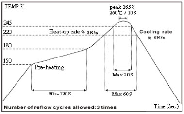
| Solderability | The electrodes shall be at least 90% covered with new solder coating | Lead-free inductor: after fluxing (alpha 100 or equiv), inductor shall be dipped in a melted solder bath at 245 ± 5°C, 5 ± 0.5 seconds |
| Resistance to Soldering Heat | Appearance: No damage | Pre-heating: 150°C, 1min. Solder Temperature: 260 ± 5°C Immersion Time: 10 ± 1 seconds |
| Vibration | Appearance: No damage L change: within ± 10% Q change: within ± 30% DCR: within specification | Test device shall be soldered on the substrate Oscillation Frequency: 10 to 55 to 10Hz for 1 min. Amplitude: 1.5 mm Time: 2 hrs for each axis (X, Y & Z), total 6 hrs |
Climatic Test
| Item | Requirement | Test Method | |||||||||||||||
|---|---|---|---|---|---|---|---|---|---|---|---|---|---|---|---|---|---|
| Temperature Cycle | Appearance: No damage L change: within ± 10% Q change: within ± 30% DCR: within specification | One cycle:
Total: 100 cycles | |||||||||||||||
| Damp Heat with Load | Temperature: 40 ± 2°C Relative Humidity: 90 ~ 95% Time: 1000 hrs Measured after exposure in the room condition for 24 hrs | ||||||||||||||||
| High Temperature Storage | Temperature: 85 ± 3°C Applied Current: Rated Current Time: 1000 hrs Measured after exposure in the room condition for 24 hrs | ||||||||||||||||
| Low Temperature Storage | Temperature: -25 ± 3°C Time: 1000 hrs Measured after exposure in the room condition for 24 hrs |
☑ Storage Temperature: 15 ~ 28°C; Humidity < 80%RH
☑ Operating Temperature Range: -40 ~ +85°C
Packaging Quantity & Reel Specifications (Unit : mm)
| Type | Ø A | Ø B | Ø C | W | T | Quantity (EA) | 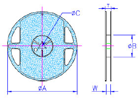 |
|---|---|---|---|---|---|---|---|
| NL03 | 178 ± 2.0 | 60 ± 0.5 | 13 ± 0.3 | 9 ± 0.3 | 12 ± 1.0 | 4000 | |
| NL05 | 178 ± 2.0 | 60 ± 0.5 | 13 ± 0.3 | 9 ± 0.3 | 12 ± 1.0 | 2000 | |
| NL08 | 178 ± 2.0 | 60 ± 0.5 | 13 ± 0.3 | 9 ± 0.3 | 12 ± 1.0 | 2000 | |
| NL10 | 178 ± 2.0 | 60 ± 0.5 | 13 ± 0.3 | 9 ± 0.3 | 12 ± 1.0 | 2000 | |
| NL12 | 178 ± 2.0 | 80 ± 0.5 | 13 ± 0.3 | 13.2 ± 0.3 | 16 ± 1.0 | 500 | |
| NL20 | 330 ± 2.0 | 100 ± 0.5 | 13 ± 0.3 | 17.4 ± 0.3 | 22 ± 1.0 | 1000 |
Embossed Plastic Tape Specifications (Unit : mm)
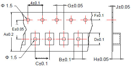
| Type | A | B | C | D | E | F | G | H | J |
|---|---|---|---|---|---|---|---|---|---|
| NL03 | 8 | 1.25 | 4 | 1.90 | 3.5 | 1.75 | 2 | 1.00 | 0.23 |
| NL05 | 8 | 1.85 | 4 | 2.55 | 3.5 | 1.75 | 2 | 1.45 | 0.23 |
| NL08 | 8 | 2.80 | 4 | 2.95 | 3.5 | 1.75 | 2 | 2.22 | 0.23 |
| NL10 | 8 | 2.96 | 4 | 3.60 | 3.5 | 1.75 | 2 | 2.40 | 0.23 |
| NL12 | 12 | 3.30 | 8 | 5.00 | 5.5 | 1.75 | 2 | 3.50 | 0.30 |
| NL20 | 16 | 5.35 | 12 | 6.10 | 7.5 | 1.75 | 2 | 5.50 | 0.35 |
Leader / Trailer Tape
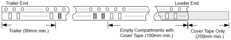
Cover Tape Peel Strength
The force for tearing off cover tape is 0.1 ~ 0.6 (N) in the arrow direction at the following conditions: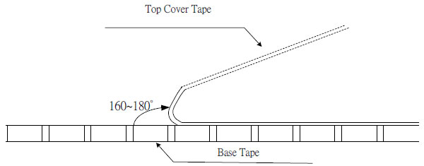

Thin film Precision resistor 0.01%, TC2ppm, wirebondale, Anti-Crossive, MELF. Current sensing, Metal...
Read More
Ceramic high frequency chip inductors, small size to 01005. Thin film, multilayer, wirewound , ferrite...
Read More
Multilayer Ceramic capacitor offers high Voltage, high frequency, low noise, High Q, Low TCR. NPO, X7R,...
Read More