


APLICAÇÕES AUTOMOTIVAS
Resistor de precisão de filme fino 0,01%, TC2ppm, wirebondale, Anti-Corrosivo, MELF. Detecção de corrente,...
consulte Mais informaçãoCom sede em Taiwan, Viking Tech Corporation é um dos principais fabricantes de Indutor de Chip Multicamadas (Série CL-S CL02JTR15-S) desde 1997.TS16949/ ISO9001/ ISO1400, atendem aos padrões AEC-Q200, e os produtos são utilizados para aplicações automotivas e de dispositivos eletrônicos.Viking fornece resistores de precisão anti-enxofre, anti-surge, de pulso, alta tensão, alta potência, incluindo resistores de filme fino/grosso, resistores automotivos, resistores melf e resistores de detecção de corrente.Indutores de baixo ruído, baixo TC e alta potência, como indutores RF, indutores de chip, indutores de potência, indutores variáveis, indutores de chip de ferrite, indutores blindados, indutores enrolados em fio e indutores de mergulho.Viking tem oferecido aos clientes resistores de potência, indutores de potência e capacitores eletrolíticos de alumínio de alta qualidade com uma sólida reputação.Com mais de 20 anos de experiência, Viking é especializada na fabricação de Resistor de Filme Fino, Resistor de Chip, Indutor de Potência, Resistor de Detecção de Corrente, Resistor de Filme Grosso, Capacitor de Chip e Substrato Cerâmico.
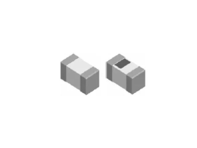
Indutor de chip cerâmico multicamada, alta frequência, indutor RF para alta SRF, excelente Q, estabilidade térmica superior. Indutância estável em circuitos de alta frequência. Design altamente estável para necessidades críticas.
CL Series0402 ±5%nH 150nHμH 3 Ω 150mA 8 0.55GHz
| Tamanho | Tolerância | Indutância | Condição de Teste | DCR (Ω) máx. | IDC (mA) | Q | SRF |
|---|---|---|---|---|---|---|---|
| 0402 | ±5% | 150nH | 100MHz | 3 | 150 | 8 | 0.55GHz |
CL01-S Multilayer Chip Inductors / High Q Type
| Inductance (nH) | Tolerance | Quality Factor min. |
Test Freq. (MHz) |
Test Voltage (mV) |
SRF (GHz) min. |
RDC (Ω) max. |
IDC (mA) max. |
|---|---|---|---|---|---|---|---|
| 0.6 | ± 0.1nH, ± 0.2nH, ± 0.3nH | 14 | 500 | 50 | 10.00 | 0.05 | 1000 |
| 0.7 | ± 0.1nH, ± 0.2nH, ± 0.3nH | 14 | 500 | 50 | 10.00 | 0.05 | 1000 |
| 0.8 | ± 0.1nH, ± 0.2nH, ± 0.3nH | 14 | 500 | 50 | 10.00 | 0.06 | 1000 |
| 0.9 | ± 0.1nH, ± 0.2nH, ± 0.3nH | 14 | 500 | 50 | 10.00 | 0.06 | 800 |
| 1.0 | ± 0.1nH, ± 0.2nH, ± 0.3nH | 14 | 500 | 50 | 10.00 | 0.07 | 800 |
| 1.1 | ± 0.1nH, ± 0.2nH, ± 0.3nH | 14 | 500 | 50 | 10.00 | 0.07 | 800 |
| 1.2 | ± 0.1nH, ± 0.2nH, ± 0.3nH | 14 | 500 | 50 | 10.00 | 0.10 | 800 |
| 1.3 | ± 0.1nH, ± 0.2nH, ± 0.3nH | 14 | 500 | 50 | 10.00 | 0.10 | 700 |
| 1.4 | ± 0.1nH, ± 0.2nH, ± 0.3nH | 14 | 500 | 50 | 10.00 | 0.10 | 700 |
| 1.5 | ± 0.1nH, ± 0.2nH, ± 0.3nH | 14 | 500 | 50 | 10.00 | 0.10 | 650 |
| 1.6 | ± 0.1nH, ± 0.2nH, ± 0.3nH | 14 | 500 | 50 | 10.00 | 0.10 | 650 |
| 1.7 | ± 0.1nH, ± 0.2nH, ± 0.3nH | 14 | 500 | 50 | 10.00 | 0.10 | 650 |
| 1.8 | ± 0.1nH, ± 0.2nH, ± 0.3nH | 14 | 500 | 50 | 9.00 | 0.15 | 650 |
| 2.0 | ± 0.1nH, ± 0.2nH, ± 0.3nH | 14 | 500 | 50 | 8.50 | 0.15 | 650 |
| 2.2 | ± 0.1nH, ± 0.2nH, ± 0.3nH | 14 | 500 | 50 | 7.50 | 0.15 | 650 |
| 2.4 | ± 0.1nH, ± 0.2nH, ± 0.3nH | 14 | 500 | 50 | 7.50 | 0.15 | 550 |
| 2.6 | ± 0.1nH, ± 0.2nH, ± 0.3nH | 14 | 500 | 50 | 7.50 | 0.20 | 550 |
| 2.7 | ± 0.1nH, ± 0.2nH, ± 0.3nH | 14 | 500 | 50 | 7.50 | 0.20 | 550 |
| 2.8 | ± 0.1nH, ± 0.2nH, ± 0.3nH | 14 | 500 | 50 | 7.50 | 0.20 | 500 |
| 3.0 | ± 0.1nH, ± 0.2nH, ± 0.3nH | 14 | 500 | 50 | 7.50 | 0.20 | 450 |
| 3.3 | ± 0.1nH, ± 0.2nH, ± 0.3nH | 14 | 500 | 50 | 7.50 | 0.25 | 450 |
| 3.6 | ± 0.1nH, ± 0.2nH, ± 0.3nH | 14 | 500 | 50 | 6.50 | 0.25 | 400 |
| 3.9 | ± 0.1nH, ± 0.2nH, ± 0.3nH | 14 | 500 | 50 | 6.50 | 0.25 | 400 |
| 4.3 | ± 0.1nH, ± 0.2nH, ± 0.3nH | 14 | 500 | 50 | 6.00 | 0.35 | 350 |
| 4.7 | ± 0.1nH, ± 0.2nH, ± 0.3nH | 14 | 500 | 50 | 6.00 | 0.40 | 350 |
| 5.1 | ± 0.1nH, ± 0.2nH, ± 0.3nH | 14 | 500 | 50 | 5.50 | 0.40 | 350 |
| 5.6 | ± 0.1nH, ± 0.2nH, ± 0.3nH | 14 | 500 | 50 | 5.00 | 0.40 | 350 |
| 6.2 | ± 0.1nH, ± 0.2nH, ± 0.3nH | 14 | 500 | 50 | 5.00 | 0.40 | 300 |
| 6.8 | ± 3%, ± 5% | 14 | 500 | 50 | 4.50 | 0.50 | 300 |
| 7.5 | ± 3%, ± 5% | 14 | 500 | 50 | 4.00 | 0.50 | 300 |
| 8.2 | ± 3%, ± 5% | 14 | 500 | 50 | 4.00 | 0.50 | 250 |
| 9.1 | ± 3%, ± 5% | 14 | 500 | 50 | 4.00 | 0.70 | 250 |
| 10 | ± 3%, ± 5% | 14 | 500 | 50 | 4.00 | 0.70 | 250 |
| 12 | ± 3%, ± 5% | 13 | 500 | 50 | 3.50 | 0.70 | 250 |
| 15 | ± 3%, ± 5% | 13 | 500 | 50 | 3.20 | 0.85 | 250 |
| 18 | ± 3%, ± 5% | 13 | 500 | 50 | 3.00 | 1.00 | 200 |
| 20 | ± 3%, ± 5% | 13 | 500 | 50 | 2.20 | 1.10 | 150 |
| 22 | ± 3%, ± 5% | 13 | 500 | 50 | 2.20 | 1.20 | 150 |
| 27 | ± 3%, ± 5% | 13 | 500 | 50 | 2.20 | 1.50 | 140 |
| 33 | ± 3%, ± 5% | 12 | 300 | 50 | 1.80 | 1.80 | 120 |
| 36 | ± 3%, ± 5% | 12 | 300 | 50 | 1.70 | 2.00 | 120 |
| 39 | ± 3%, ± 5% | 12 | 300 | 50 | 1.60 | 2.00 | 100 |
| 43 | ± 3%, ± 5% | 12 | 300 | 50 | 1.60 | 2.20 | 100 |
| 47 | ± 3%, ± 5% | 12 | 300 | 50 | 1.50 | 2.20 | 100 |
| 56 | ± 3%, ± 5% | 12 | 300 | 50 | 1.20 | 2.50 | 100 |
| 68 | ± 3%, ± 5% | 12 | 300 | 50 | 1.00 | 3.20 | 120 |
| 75 | ± 3%, ± 5% | 11 | 300 | 50 | 1.00 | 3.60 | 100 |
| 82 | ± 3%, ± 5% | 11 | 300 | 50 | 1.00 | 3.80 | 100 |
| 91 | ± 3%, ± 5% | 11 | 300 | 50 | 0.90 | 3.80 | 80 |
| 100 | ± 3%, ± 5% | 11 | 300 | 50 | 0.80 | 4.00 | 80 |
| 120 | ± 3%, ± 5% | 10 | 300 | 50 | 0.80 | 5.00 | 80 |
☑ Operating temperature range: -55 ~ +125°C
☑ L/Q Test equipment: E4991B + 16196a
☑ Test compensation: Short bar residual inductance 0.48nH
CL02-S01 Multilayer Chip Inductors / High Q Type
| Inductance (nH) | Tolerance | Quality Factor min. |
Test Freq. (MHz) |
Test Voltage (mV) |
SRF (MHz) min. |
RDC (Ω) max. |
IDC (mA) max. |
|---|---|---|---|---|---|---|---|
| 1.0 | ± 0.1nH | 13 | 500 | 50 | 6000 | 0.1 | 400 |
| 1.1 | ± 0.1nH | 13 | 500 | 50 | 6000 | 0.1 | 390 |
| 1.2 | ± 0.1nH | 13 | 500 | 50 | 600 | 0.1 | 390 |
| 1.3 | ± 0.1nH | 13 | 500 | 50 | 6000 | 0.2 | 280 |
| 1.4 | ± 0.1nH | 13 | 500 | 50 | 6000 | 0.2 | 280 |
| 1.5 | ± 0.1nH | 13 | 500 | 50 | 6000 | 0.2 | 280 |
| 1.6 | ± 0.1nH | 13 | 500 | 50 | 6000 | 0.3 | 220 |
| 1.7 | ± 0.1nH | 13 | 500 | 50 | 6000 | 0.3 | 280 |
| 1.8 | ± 0.1nH | 13 | 500 | 50 | 6000 | 0.3 | 280 |
| 1.9 | ± 0.1nH | 13 | 500 | 50 | 6000 | 0.3 | 220 |
| 2.0 | ± 0.1nH | 13 | 500 | 50 | 6000 | 0.3 | 220 |
| 2.1 | ± 0.1nH | 13 | 500 | 50 | 6000 | 0.3 | 220 |
| 2.2 | ± 0.1nH | 13 | 500 | 50 | 6000 | 0.3 | 220 |
| 2.3 | ± 0.1nH | 13 | 500 | 50 | 6000 | 0.3 | 220 |
| 2.4 | ± 0.1nH | 13 | 500 | 50 | 6000 | 0.3 | 220 |
| 2.5 | ± 0.1nH | 13 | 500 | 50 | 6000 | 0.3 | 220 |
| 2.6 | ± 0.1nH | 13 | 500 | 50 | 6000 | 0.3 | 220 |
| 2.7 | ± 0.1nH | 13 | 500 | 50 | 6000 | 0.3 | 220 |
| 2.8 | ± 0.1nH | 13 | 500 | 50 | 6000 | 0.4 | 190 |
| 2.9 | ± 0.1nH | 13 | 500 | 50 | 6000 | 0.4 | 190 |
| 3.0 | ± 0.1nH | 13 | 500 | 50 | 6000 | 0.4 | 190 |
| 3.1 | ± 0.1nH | 13 | 500 | 50 | 6000 | 0.4 | 190 |
| 3.2 | ± 0.1nH | 13 | 500 | 50 | 6000 | 0.4 | 190 |
| 3.3 | ± 0.1nH | 13 | 500 | 50 | 6000 | 0.5 | 190 |
| 3.4 | ± 0.1nH | 13 | 500 | 50 | 6000 | 0.5 | 190 |
| 3.5 | ± 0.1nH | 13 | 500 | 50 | 6000 | 0.5 | 190 |
| 3.6 | ± 0.1nH | 13 | 500 | 50 | 6000 | 0.5 | 190 |
| 3.7 | ± 0.1nH | 13 | 500 | 50 | 6000 | 0.5 | 190 |
| 3.8 | ± 0.1nH | 13 | 500 | 50 | 6000 | 0.5 | 170 |
| 3.9 | ± 0.1nH | 13 | 500 | 50 | 6000 | 0.4 | 170 |
| 4.3 | ± 0.1nH | 13 | 500 | 50 | 6000 | 0.6 | 160 |
| 4.7 | ± 0.1nH | 13 | 500 | 50 | 6000 | 0.6 | 160 |
| 5.1 | ± 0.1nH | 13 | 500 | 50 | 6000 | 0.7 | 140 |
| 5.6 | ± 0.1nH | 13 | 500 | 50 | 6000 | 0.7 | 140 |
| 6.2 | ± 0.1nH | 13 | 500 | 50 | 6000 | 0.9 | 130 |
| 6.8 | ± 0.1nH | 13 | 500 | 50 | 6000 | 0.9 | 130 |
| 7.5 | ± 0.1nH | 13 | 500 | 50 | 5500 | 1.1 | 110 |
| 8.2 | ± 0.1nH | 13 | 500 | 50 | 5500 | 1.1 | 110 |
| 9.1 | ± 0.1nH | 13 | 500 | 50 | 4500 | 1.3 | 100 |
| 10 | ± 2% | 13 | 500 | 50 | 4500 | 1.3 | 100 |
| 12 | ± 2% | 13 | 500 | 50 | 3700 | 1.6 | 90 |
| 15 | ± 2% | 13 | 500 | 50 | 3300 | 1.8 | 90 |
| 18 | ± 2% | 13 | 500 | 50 | 3100 | 2.0 | 80 |
| 22 | ± 2% | 13 | 500 | 50 | 2800 | 2.6 | 70 |
| 27 | ± 2% | 13 | 500 | 50 | 2500 | 3.8 | 60 |
| 33 | ± 2% | 13 | 500 | 50 | 2100 | 3.8 | 60 |
☑ Operating temperature range: -40 ~ +85°C
☑ Keysight E4991B+Testing fixture 16197A.Short bar residual inductance=0.556nH
CL02-S02 Multilayer Chip Inductors / High Q Type
| Inductance (nH) | Tolerance | L Test Freq. (MHz) |
Quality min. |
Q Test Freq. (MHz) |
Test Voltage (mV) |
SRF (MHz) min. |
RDC (Ω) max. |
IDC (mA) max. |
|---|---|---|---|---|---|---|---|---|
| 0.6 | ± 0.1nH, ± 0.2nH, ± 0.3nH | 100 | - | 250 | 50 | 15000 | 0.01 | 1200 |
| 0.7 | ± 0.1nH, ± 0.2nH, ± 0.3nH | 100 | - | 250 | 50 | 15000 | 0.02 | 1200 |
| 0.8 | ± 0.1nH, ± 0.2nH, ± 0.3nH | 100 | - | 250 | 50 | 15000 | 0.02 | 1200 |
| 0.9 | ± 0.1nH, ± 0.2nH, ± 0.3nH | 100 | - | 250 | 50 | 15000 | 0.03 | 1200 |
| 1.0 | ± 0.1nH, ± 0.2nH, ± 0.3nH | 100 | 23 | 250 | 50 | 15000 | 0.03 | 1200 |
| 1.1 | ± 0.1nH, ± 0.2nH, ± 0.3nH | 100 | 23 | 250 | 50 | 14000 | 0.03 | 1200 |
| 1.2 | ± 0.1nH, ± 0.2nH, ± 0.3nH | 100 | 23 | 250 | 50 | 13000 | 0.03 | 1200 |
| 1.3 | ± 0.1nH, ± 0.2nH, ± 0.3nH | 100 | 23 | 250 | 50 | 12000 | 0.03 | 1200 |
| 1.4 | ± 0.1nH, ± 0.2nH, ± 0.3nH | 100 | 12 | 250 | 50 | 13000 | 0.04 | 1200 |
| 1.5 | ± 0.1nH, ± 0.2nH, ± 0.3nH | 100 | 23 | 250 | 50 | 11000 | 0.04 | 1000 |
| 1.6 | ± 0.1nH, ± 0.2nH, ± 0.3nH | 100 | 23 | 250 | 50 | 10000 | 0.04 | 1000 |
| 1.7 | ± 0.1nH, ± 0.2nH, ± 0.3nH | 100 | 23 | 250 | 50 | 10000 | 0.04 | 1000 |
| 1.8 | ± 0.1nH, ± 0.2nH, ± 0.3nH | 100 | 23 | 250 | 50 | 9000 | 0.04 | 1000 |
| 1.9 | ± 0.1nH, ± 0.2nH, ± 0.3nH | 100 | 23 | 250 | 50 | 8000 | 0.05 | 1000 |
| 2.0 | ± 0.1nH, ± 0.2nH, ± 0.3nH | 100 | 23 | 250 | 50 | 8000 | 0.05 | 1000 |
| 2.1 | ± 0.1nH, ± 0.2nH, ± 0.3nH | 100 | 23 | 250 | 50 | 8000 | 0.06 | 1000 |
| 2.2 | ± 0.1nH, ± 0.2nH, ± 0.3nH | 100 | 23 | 250 | 50 | 8000 | 0.06 | 1000 |
| 2.3 | ± 0.1nH, ± 0.2nH, ± 0.3nH | 100 | 23 | 250 | 50 | 7000 | 0.07 | 1000 |
| 2.4 | ± 0.1nH, ± 0.2nH, ± 0.3nH | 100 | 23 | 250 | 50 | 6500 | 0.07 | 1000 |
| 2.5 | ± 0.1nH, ± 0.2nH, ± 0.3nH | 100 | 23 | 250 | 50 | 6500 | 0.06 | 900 |
| 2.6 | ± 0.1nH, ± 0.2nH, ± 0.3nH | 100 | 23 | 250 | 50 | 6500 | 0.07 | 900 |
| 2.7 | ± 0.1nH, ± 0.2nH, ± 0.3nH | 100 | 23 | 250 | 50 | 6500 | 0.07 | 900 |
| 2.8 | ± 0.1nH, ± 0.2nH, ± 0.3nH | 100 | 23 | 250 | 50 | 6500 | 0.07 | 900 |
| 2.9 | ± 0.1nH, ± 0.2nH, ± 0.3nH | 100 | 23 | 250 | 50 | 6500 | 0.08 | 900 |
| 3.0 | ± 0.1nH, ± 0.2nH, ± 0.3nH | 100 | 23 | 250 | 50 | 6000 | 0.09 | 900 |
| 3.1 | ± 0.1nH, ± 0.2nH, ± 0.3nH | 100 | 23 | 250 | 50 | 6000 | 0.09 | 900 |
| 3.2 | ± 0.1nH, ± 0.2nH, ± 0.3nH | 100 | 23 | 250 | 50 | 6000 | 0.09 | 900 |
| 3.3 | ± 0.1nH, ± 0.2nH, ± 0.3nH | 100 | 23 | 250 | 50 | 6000 | 0.08 | 900 |
| 3.4 | ± 0.1nH, ± 0.2nH, ± 0.3nH | 100 | 23 | 250 | 50 | 6000 | 0.09 | 900 |
| 3.5 | ± 0.1nH, ± 0.2nH, ± 0.3nH | 100 | 23 | 250 | 50 | 5800 | 0.09 | 900 |
| 3.6 | ± 0.1nH, ± 0.2nH, ± 0.3nH | 100 | 23 | 250 | 50 | 5500 | 0.09 | 900 |
| 3.7 | ± 0.1nH, ± 0.2nH, ± 0.3nH | 100 | 23 | 250 | 50 | 5500 | 0.10 | 900 |
| 3.8 | ± 0.1nH, ± 0.2nH, ± 0.3nH | 100 | 23 | 250 | 50 | 5000 | 0.10 | 900 |
| 3.9 | ± 0.1nH, ± 0.2nH, ± 0.3nH | 100 | 23 | 250 | 50 | 5000 | 0.09 | 800 |
| 4.1 | ± 0.1nH, ± 0.2nH, ± 0.3nH | 100 | 23 | 250 | 50 | 5000 | 0.10 | 800 |
| 4.3 | ± 0.1nH, ± 0.2nH, ± 0.3nH | 100 | 23 | 250 | 50 | 5000 | 0.10 | 800 |
| 4.7 | ± 0.1nH, ± 0.2nH, ± 0.3nH | 100 | 23 | 250 | 50 | 5000 | 0.11 | 800 |
| 4.9 | ± 0.1nH, ± 0.2nH, ± 0.3nH | 100 | 23 | 250 | 50 | 5000 | 0.11 | 800 |
| 5.1 | ± 0.1nH, ± 0.2nH, ± 0.3nH | 100 | 23 | 250 | 50 | 4500 | 0.12 | 800 |
| 5.4 | ± 0.1nH, ± 0.2nH, ± 0.3nH | 100 | 23 | 250 | 50 | 4500 | 0.13 | 800 |
| 5.6 | ± 0.1nH, ± 0.2nH, ± 0.3nH | 100 | 23 | 250 | 50 | 4500 | 0.13 | 800 |
| 5.8 | ± 0.1nH, ± 0.2nH, ± 0.3nH | 100 | 23 | 250 | 50 | 4000 | 0.13 | 700 |
| 6.0 | ± 0.1nH, ± 0.2nH, ± 0.3nH | 100 | 23 | 250 | 50 | 4000 | 0.13 | 700 |
| 6.2 | ± 0.1nH, ± 0.2nH, ± 0.3nH | 100 | 23 | 250 | 50 | 4000 | 0.13 | 700 |
| 6.5 | ± 2%, ± 3%, ± 5% | 100 | 23 | 250 | 50 | 4000 | 0.14 | 700 |
| 6.8 | ± 2%, ± 3%, ± 5% | 100 | 23 | 250 | 50 | 4000 | 0.14 | 700 |
| 7.3 | ± 2%, ± 3%, ± 5% | 100 | 23 | 250 | 50 | 4000 | 0.16 | 600 |
| 7.5 | ± 2%, ± 3%, ± 5% | 100 | 23 | 250 | 50 | 4000 | 0.16 | 600 |
| 8.2 | ± 2%, ± 3%, ± 5% | 100 | 23 | 250 | 50 | 3600 | 0.16 | 550 |
| 8.7 | ± 2%, ± 3%, ± 5% | 100 | 23 | 250 | 50 | 3500 | 0.17 | 550 |
| 9.1 | ± 2%, ± 3%, ± 5% | 100 | 23 | 250 | 50 | 3400 | 0.17 | 550 |
| 9.5 | ± 2%, ± 3%, ± 5% | 100 | 23 | 250 | 50 | 3300 | 0.21 | 500 |
| 10 | ± 2%, ± 3%, ± 5% | 100 | 23 | 250 | 50 | 3300 | 0.19 | 500 |
| 11 | ± 2%, ± 3%, ± 5% | 100 | 23 | 250 | 50 | 3000 | 0.22 | 450 |
| 12 | ± 2%, ± 3%, ± 5% | 100 | 23 | 250 | 50 | 2800 | 0.24 | 450 |
| 13 | ± 2%, ± 3%, ± 5% | 100 | 23 | 250 | 50 | 2800 | 0.26 | 400 |
| 15 | ± 2%, ± 3%, ± 5% | 100 | 23 | 250 | 50 | 2300 | 0.28 | 400 |
☑ Operating temperature range: -55 ~ +125°C
☑ L/Q test equipment: Keysight E4991B+Testing fixture 16197A.Short bar residual inductance=0.556nH
CL02-S Multilayer Chip Inductors / High Frequency Type
| Inductance (nH) | Tolerance | Quality Factor /min. | L/Q Freq. (MHz) | Q (Typical) Freq. (MHz) | SRF min. (GHz) | RDC (Ω) max. | IDC (mA) max. | |||||
|---|---|---|---|---|---|---|---|---|---|---|---|---|
| 100 | 300 | 500 | 800 | 1000 | 1800 | |||||||
| 1.0 | ± 0.3nH | 5 | 100 | 9 | 16 | 20 | 25 | 28 | 31 | >8.50 | 0.10 | 500 |
| 1.2 | ± 0.3nH | 5 | 100 | 9 | 15 | 18 | 24 | 27 | 31 | >8.50 | 0.12 | 500 |
| 1.5 | ± 0.3nH | 5 | 100 | 7 | 12 | 16 | 20 | 21 | 29 | >8.50 | 0.15 | 500 |
| 1.8 | ± 0.3nH | 5 | 100 | 7 | 12 | 16 | 20 | 21 | 29 | >8.50 | 0.17 | 500 |
| 2.2 | ± 0.3nH | 5 | 100 | 7 | 12 | 16 | 20 | 21 | 30 | >8.50 | 0.17 | 500 |
| 2.7 | ± 0.3nH | 5 | 100 | 7 | 12 | 16 | 20 | 21 | 29 | >8.50 | 0.20 | 500 |
| 3.3 | ± 0.3nH | 5 | 100 | 7 | 12 | 15 | 19 | 20 | 27 | >8.50 | 0.22 | 400 |
| 3.9 | ± 0.3nH | 5 | 100 | 7 | 12 | 15 | 20 | 21 | 28 | 7.50 | 0.25 | 400 |
| 4.7 | ± 0.3nH | 5 | 100 | 7 | 12 | 15 | 19 | 20 | 27 | 6.50 | 0.28 | 400 |
| 5.6 | ± 0.3nH | 5 | 100 | 8 | 12 | 15 | 20 | 22 | 30 | 6.50 | 0.30 | 400 |
| 6.8 | ± 5%, ± 10% | 5 | 100 | 8 | 12 | 15 | 20 | 22 | 30 | 6.50 | 0.35 | 400 |
| 8.2 | ± 5%, ± 10% | 5 | 100 | 8 | 12 | 15 | 19 | 21 | 30 | 6.50 | 0.38 | 350 |
| 10 | ± 5%, ± 10% | 5 | 100 | 8 | 13 | 16 | 21 | 23 | 32 | 4.70 | 0.42 | 350 |
| 12 | ± 5%, ± 10% | 5 | 100 | 8 | 13 | 16 | 20 | 23 | 27 | 4.30 | 0.47 | 350 |
| 15 | ± 5%, ± 10% | 5 | 100 | 8 | 12 | 15 | 19 | 22 | 28 | 4.00 | 0.50 | 300 |
| 18 | ± 5%, ± 10% | 5 | 100 | 8 | 13 | 16 | 21 | 24 | 32 | 4.00 | 0.60 | 250 |
| 22 | ± 5%, ± 10% | 5 | 100 | 8 | 13 | 17 | 22 | 26 | 31 | 3.50 | 0.70 | 200 |
| 27 | ± 5%, ± 10% | 5 | 100 | 8 | 14 | 18 | 23 | 26 | 32 | 3.00 | 0.80 | 200 |
| 33 | ± 5%, ± 10% | 5 | 100 | 8 | 14 | 17 | 23 | 27 | 32 | 2.50 | 0.90 | 200 |
| 39 | ± 5%, ± 10% | 5 | 100 | 8 | 14 | 18 | 23 | 27 | 32 | 2.00 | 1.00 | 200 |
| 47 | ± 5%, ± 10% | 7 | 100 | 9 | 14 | 18 | 22 | 24 | 29 | 2.40 | 2.20 | 100 |
| 56 | ± 5%, ± 10% | 7 | 100 | 9 | 14 | 18 | 23 | 24 | 29 | 2.30 | 2.50 | 100 |
| 68 | ± 5%, ± 10% | 7 | 100 | 9 | 14 | 17 | 22 | 24 | 29 | 2.20 | 2.70 | 100 |
| 82 | ± 5%, ± 10% | 7 | 100 | 8 | 13 | 17 | 20 | 20 | 16 | 2.10 | 2.90 | 100 |
| 100 | ± 5%, ± 10% | 7 | 100 | 8 | 13 | 17 | 20 | 20 | 13 | 2.00 | 3.20 | 100 |
☑ Operating temperature range: -55~+125°C
CL03-S Multilayer Chip Inductors / High Frequency Type
| Inductance (nH) | Tolerance | Quality Factor /min. | L/Q Freq. (MHz) | Q (Typical) Freq. (MHz) | SRF min. (GHz) | RDC (Ω) max. | IDC (mA) max. | |||||
|---|---|---|---|---|---|---|---|---|---|---|---|---|
| 100 | 300 | 500 | 800 | 1000 | 1800 | |||||||
| 10 | ± 5% | 8 | 100 | 10 | 22 | 28 | 35 | 39 | 45 | >6.00 | 0.6 | 500 |
| 12 | ± 5% | 8 | 100 | 10 | 18 | 23 | 26 | 32 | 42 | 6.00 | 0.7 | 500 |
| 15 | ± 5% | 8 | 100 | 12 | 22 | 28 | 35 | 39 | 42 | 5.50 | 0.8 | 500 |
| 18 | ± 5% | 8 | 100 | 10 | 18 | 22 | 25 | 30 | 43 | 5.20 | 0.9 | 300 |
| 22 | ± 5% | 8 | 100 | 12 | 21 | 27 | 34 | 37 | 37 | 5.00 | 1.0 | 300 |
| 27 | ± 5% | 8 | 100 | 10 | 18 | 24 | 26 | 32 | 38 | 4.80 | 1.2 | 300 |
| 33 | ± 5% | 8 | 100 | 12 | 21 | 27 | 33 | 35 | 31 | 4.50 | 1.4 | 300 |
| 39 | ± 5% | 8 | 100 | 11 | 20 | 26 | 32 | 34 | 29 | 4.00 | 1.5 | 200 |
| 47 | ± 5% | 8 | 100 | 12 | 20 | 26 | 31 | 34 | 27 | 3.50 | 1.6 | 200 |
| 56 | ± 5% | 8 | 100 | 11 | 20 | 26 | 31 | 34 | 24 | 3.00 | 1.8 | 200 |
| 68 | ± 5% | 8 | 100 | 10 | 18 | 21 | 24 | 28 | 20 | 2.80 | 2.0 | 200 |
| 82 | ± 5% | 8 | 100 | 10 | 19 | 22 | 26 | 26 | 15 | 2.50 | 2.2 | 200 |
| 100 | ± 5% | 8 | 100 | 10 | 19 | 24 | 27 | 25 | - | 2.00 | 2.5 | 150 |
| 120 | ± 5% | 8 | 100 | 10 | 19 | 23 | 26 | 24 | - | 1.60 | 2.8 | 150 |
| 150 | ± 5% | 8 | 100 | 10 | 18 | 24 | 26 | 23 | - | 1.40 | 3.0 | 150 |
| 180 | ± 5% | 8 | 100 | 10 | 17 | 22 | 23 | - | - | 1.00 | 3.4 | 150 |
☑ Operating temperature range: -40~+85°C
Electrical Performance Test
| Item | Requirement | Test Condition |
|---|---|---|
| Inductance | In Within specified tolerance | Temperature: 20 ± 1°C Relative Humidity: 45 to 85%RH Atmospheric Pressure: 86 to 106kpa Measuring equipment and fixture: 0201: E991A+HP16197A 0402/0603: E991A + HP16192A Test Signal: -20dBm or 50mV Test compensation(for 0201 high Q): Product true value = test value + compensation value. for L < 3.6nH, compensation value is 0.25nH; for 3.6nH ≤ L<6.8nH, compensation value is 0.43nH; for 6.8 nH ≤ L<9.1nH, compensation value is 0.5nH; for 9.1 nH ≤ L<33nH, compensation value is 0.85nH; for L ≥ 33nH, compensation value is 0.85nH; |
| Q Value | In accordance with electrical specification | Temperature: 20 ± 1°C Relative Humidity: 45 to 85%RH Atmospheric Pressure: 86 to 106kpa |
| DC Resistance | In accordance with electrical specification | Temperature: 20 ± 1°C Relative Humidity: 45 to 85%RH Atmospheric Pressure: 86 to 106kpa Measuring equipment: HP 4338 |
Mechanical Characteristies Test
| Item | Requirement | Test Condition |
|---|---|---|
| Bending Strength | No mechanical damage shall be observed | Flexure: 2mm Pressurizing speed: 0.5mm/sec Keep time: 30sec 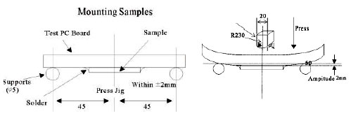 |
| Solderability | No visible mechanical damage Wetting shall exceed 75% coverage for 0201 series; exceed 95% coverage for others |
Solder temperature: 240 ± 2°C Time: 3 seconds Solder: Sn/3.0Ag/0.5Cu Flux: 25% resin and 75% ethanol in weight |
| Resistance to Soldering Heat | No visible mechanical damage Wetting shall exceed 75% coverage for 0201 series; exceed 95% coverage for others Inductance change: within ± 10% Q change: within ± 20% |
Solder temperature: 260 ± 3°C Time: 5 seconds Solder: Sn/3.0Ag/0.5Cu Flux: 25% resin and 75% ethanol in weight The chip shall be stabilized at normal condition for 1~2 hours before measuring |
| Dropping | No visible mechanical damage Inductance change: within ± 10% Q change: within ± 20% |
Drop chip inductor 10 times on a concrete floor form a height of 100cm |
Climatic Test
| Item | Requirement | Test Condition |
|---|---|---|
| Thermal Shock | No visible damage Inductance variation within 10% Q variation within 20% |
0201/0402 series: -55°C for 30 ± 3 min→125°C for 30 ± 3 min 0603 series: -40°C for 30 ± 3 min→85°C for 30 ± 3 min Transforming interval: max. 20 seconds Test cycle: 100 cycles The chip shall be stabilized at normal condition for 1~2 hours Before measuring |
| Resistance to Low Temperature | Temperature: 0201/0402 series: -55 ± 2°C; 0603 series: -40 ± 2°C Time: 1000 ± 24 hours The chip shall be stabilized at normal condition for 1~2 hours Before measuring |
|
| Resistance to High Temperature | Temperature: 0201/0402 series: 125 ± 2°C; 0603 series: 85 ± 2°C Time: 1000 ± 24 hours The chip shall be stabilized at normal condition for 1~2 hours Before measuring |
|
| Damp Heat (Steady States) | Temperature: 60 ± 2°C Humidity: 90 ~ 95% RH. Time: 1000 ± 24 hours The chip shall be stabilized at normal condition for 1~2 hours Before measuring |
|
| Loading Under Damp Heat | Temperature: 60 ± 2°C Humidity: 90~95% RH. Time: 1000 ± 24 hours Applied current: Rated current The chip shall be stabilized at normal condition for 1~2 hours Before measuring |
|
| Loading at High Temperature (Life Test) | Temperature: 0201/0402 series: 125 ± 2°C; 0603 series: 85 ± 2°C Time: 1000 ± 24 hours Applied current: Rated current The chip shall be stabilized at normal condition for 1~2 hours Before measuring |
☑ Storage Temperature: 15 ~ 28°C; Humidity < 80%RH
Reel Dimension (Unit : mm)
| Type | A | B | C | W | T | Quantity (EA) | 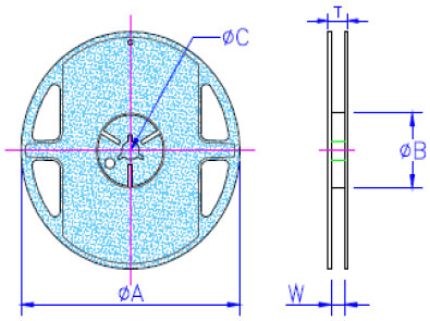 |
|---|---|---|---|---|---|---|---|
| CLE5-S | 178 ± 2 | 50 or more | 13.0 ± 0.20 | 8.4 +1.5/-0 | 14.4 max | 20,000 | |
| CL01-S | 178 ± 1 | 60.0 ± 0.5 | 13.0 ± 0.20 | 9.00 ± 0.5 | 12.0 ± 0.15 | 15,000 | |
| CL02-S | 178 ± 1 | 57.0 ± 2 | 12.5 ± 1.50 | 8.00 +1.5/-0 | 12.0 ± 0.15 | 10,000 | |
| CL03-S | 178 ± 1 | 60.0 ± 0.5 | 13.0 ± 0.20 | 9.00 ± 0.5 | 12.0 ± 0.15 | 4,000 |
Tape Specifications (Unit : mm)
| Type | A | B | T | W | P | F | K | Tape | 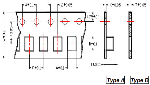 |
|---|---|---|---|---|---|---|---|---|---|
| CLE5-S | 0.25 ± 0.03 | 0.46 ± 0.03 | 0.31 ± 0.03 | 8 | 2 | 3.5 | - | B | |
| CL01-S | 0.40 | 0.70 | 0.50 | 8 | 2 | 3.5 | - | B | |
| CL02-S | 0.65 | 1.15 | 0.80 | 8 | 2 | 3.5 | - | B | |
| CL03-S | 1.10 | 1.80 | 1.10 | 8 | 4 | 3.5 | - | B |

Resistor de precisão de filme fino 0,01%, TC2ppm, wirebondale, Anti-Corrosivo, MELF. Detecção de corrente,...
consulte Mais informação
Indutores de chip de alta frequência cerâmicos, de tamanho pequeno até 01005. Filme fino, multicamada,...
consulte Mais informação
O capacitor cerâmico multicamada oferece alta tensão, alta frequência, baixo ruído, alta Q, baixo...
consulte Mais informação